Perform the procedures indicated in the table below.
Static Checks Just After Vehicle Receipt
|
Step |
Check point |
|
1. Appearance |
(1) If the vehicle is covered with protective coating, visually check the vehicle body for damage and dents. If the protective coating has been removed, visually inspect the body paints for small areas of damage or rust. (2) Visually check the glass and light lenses for any damage, cracks or excessive gaps between body sheet metal. (3) Visually check the plated parts for any damage. |
|
2. Tire |
(1) Check the tires for damage, defective, and dents on wheels. (2) Check the tire air pressure. |
|
3. Fuse installation |
If the vehicle is about to be delivered to customer, attach a room light fuse. |
|
4. Lock/unlock and open/close operation checks of doors |
(1) Using the key, check the door can be locked or unlocked normally. (2) Open and close all doors to check that there are no defective. |
|
5. Double lock |
Check that double lock operates normally. |
|
6. Child safety lock system |
Check the child safety lock system operates normally. |
|
7. Lock/unlock and open/close operation checks of rear gate |
(1) Check if the rear gate can be unlocked normally through the emergency hole. For model with double lock, remove the screw and cap using a screwdriver, and then check if the rear gate can be unlocked properly. (2) Open and close the rear gate to see that there are no problems. |
|
8. Fuel filler lid opener lock release lever |
Operate the fuel lid opener to check that the fuel lid is unlocked normally. |
|
9. Accessory |
Check that the following accessories are provided. • Owner’s manual • Warranty booklet • Maintenance note • Spare key • Key number plate • Security ID plate • Jack • Tool set • Spare tire • Towing hook (Eye bolt) |
|
10. Front hood lock release system |
Operate the front hood lock release lever to check that the front hood opens normally. |
|
11. Battery |
Check the battery for any abnormal conditions such as rust and trace of battery fluid leaks. |
|
12. Brake fluid |
Check the fluid amount. |
|
13. Engine oil |
Check the oil amount. |
|
14. Transmission gear oil |
Check that the transmission gear oil level is normal. |
|
15. AT front differential oil |
Check the AT front differential oil amount. |
|
16. Engine coolant |
Check the engine coolant amount. |
|
17. Clutch fluid |
Check the clutch fluid amount. |
|
18. Window washer fluid |
Check the window washer fluid amount. |
|
19. Front hood latch |
Check that the front hood is closed and locked normally. |
|
20. Keyless entry system |
Check that the keyless entry system operates normally. |
|
21. Keyless access function |
Check the operation of the keyless access function. |
|
22. Seat |
(1) Check the seat surfaces for stains or dirt. (2) Check the seat installation conditions and functionality. |
|
23. Seat belt |
Check the seat belt installation conditions and functionality. |
Checks with the Engine Running
|
Step |
Check point |
|
24. Delivery (test) mode connector |
Check that the delivery (test) mode connector is disconnected. |
|
25. Immobilizer system |
(1) Check that the engine starts with all keys that are equipped on vehicle. (2) 60 seconds after turning ignition switch from ON to ACC or OFF, or immediately after removing the key, check that the security indicator light is blinking. |
|
26. Starting condition |
Start the engine and check that the engine starts smoothly. |
|
27. Exhaust system |
Check that the exhaust noise is normal and no leaks are found. |
|
28. Indicator and warning lights |
Check that all indicator lights and warning lights operate normally. |
|
29. Heater & ventilation |
Check that the heater & ventilation system operates normally. |
|
30. Air conditioner |
Check that the air conditioner operates normally. |
|
31. Clock |
Check that the clock operates normally. |
|
32. Antenna |
Install the antenna. |
|
33. Audio |
Check the radio and CD player for normal operation. |
|
34. Navigation system |
(1) Check all display functions for normal operation. (2) Check the map disc (DVD) are provided on vehicle. (3) Check that the navigation system operates normally. |
|
35. Front accessory power supply socket |
Check that the front accessory power supply socket operates normally. |
|
36. Lighting system |
Check that the lighting system operates normally. |
|
37. Illumination control |
Check that the illumination control operates normally. |
|
38. Window washer |
Check that the window washer system operates normally. |
|
39. Headlight washer |
Check the headlight washer operation. |
|
40. Wiper |
Check that the wiper system operates normally. |
|
41. Wiper deicer |
Check that the wiper deicer operates normally. |
|
42. Power window |
Check that the power window operates normally. |
|
43. Outer mirror |
Check that the remote control mirror operates normally. |
Dynamic Test with the Vehicle Running
|
Step |
Check point |
|
44. Brake test |
Check the foot brake for normal operations. |
|
45. Parking brake |
Check the parking brake for normal operations. |
|
46. AT shift control |
Check that the AT shift patterns are correct. |
|
47. Cruise control |
Check that the cruise control system operates normally. |
Checks after Dynamic Test
|
Step |
Check point |
|
48. ATF level |
Check that the ATF level is correct. |
|
49. Power steering system |
• Check that the power steering fluid level is normal. (Hydraulic power steering model) • Check the malfunction steering warning light does not illuminate. (Electric power steering model) |
|
50. Fluid leakage |
Check for fluid/oil leaks. |
|
51. Water leakage |
Spray the vehicle with water and check for water leaks. |
|
52. Appearance 2 |
(1) Remove the protective coat. (If attached) (2) Check the body paints for damage and stain. (3) Check the plated parts for damage and rust. |
1. If the vehicle is covered with protective coating, visually check the vehicle body for damage and dents.
2. If there is no protective coat, check the body paints for damage or stains in detail and repair as necessary.
3. Check the window glass, door glass, and lights for any cracks or damage, and replace as necessary.
4. Check the plated parts, such as the grilles and door knobs, for damage or loss of gloss and replace the parts as necessary.
1. Check the outer side surface of the tire damage.
2. Check the tire size, spare tire and tire air pressure described on the air pressure label.
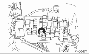
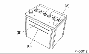
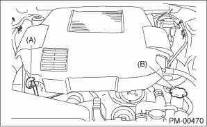
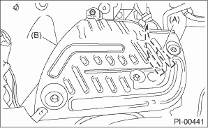
Fuses for the room light circuit on initially delivered vehicles are removed to prevent battery discharge. Attach the 20 A fuse (A) as shown in the figure.
4. DOOR LOCK/UNLOCK AND OPEN/CLOSE OPERATIONS
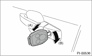
1. Using the key, lock and unlock the door several times to check for normal operation. Open and close the door several times for smooth movement.
• LHD model
|
(A) |
Unlock |
|
(B) |
Lock |
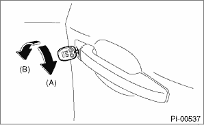
• RHD model
|
(A) |
Unlock |
|
(B) |
Lock |
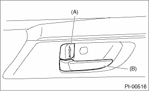
2. Close the door of driver seat completely, and place the door lock knob (A) to the lock position. Then pull the inner remote (B) to ensure that doors will not open.
For other doors, place the door lock knob (A) to lock position and then pull the inner remote (B) to ensure that doors will not open.
|
(A) |
Door lock knob |
|
(B) |
Inner remote |
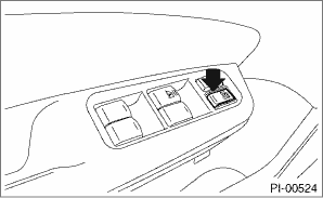
3. Press the driver’s power door lock switch to the lock side. Check that all doors (including the rear gate) lock.
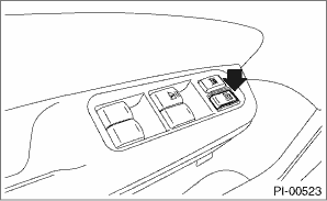
4. Press the driver’s power door lock switch to the unlock side. Check that all doors (including the rear gate) unlock.
1. Fully open all windows.
2. Remove the key.
3. Lock the doors using key or keyless transmitter.
4. Check that all doors including rear gate are not unlocked when pressing the power door lock switch to unlock side.
5. Place the door lock knob to the unlock position, then pull inner remote to ensure that doors will not open. For other doors, ensure that the doors will not open.
6. Check that double lock is unlocked for all doors and all doors are unlocked then rear gate is unlocked when ignition key is turned ON at double lock status.
1. Set the child safety lock on both rear doors to the lock position.
2. Close the rear doors completely.
3. Check that the lock levers of the rear doors are in the unlock position. Then, pull inner remote of rear doors to ensure that doors will not open.
4. Pull the outer handles of the rear doors to ensure that doors will open.
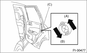
|
(A) |
Unlock |
|
(B) |
Lock |
|
(C) |
Child safety lock |
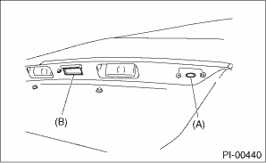
7. REAR GATE LOCK/UNLOCK AND OPEN/CLOSE OPERATIONS
1. Open and close the rear gate several times for smooth movement.
2. Check the emergency lever operation. For model with double lock, remove the screw and cap using a screwdriver, and then check if the emergency lever can be unlocked properly.
(1) Remove the cover inside the rear gate.
(2) Using a screwdriver, check that the rear gate is unlocked normally.
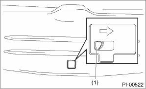
|
(1) |
Lever |
8. FUEL LID OPENER LOCK RELEASE LEVER
Operate the fuel lid opener to check that the fuel lid opens normally. Check that the filler cap is securely closed.
Check that the following accessories are provided.
• Owner’s manual
• Warranty booklet
• Maintenance note
• Spare key
• Key number plate
• Security ID plate
• Jack
• Tool set
• Spare tire
• Towing hook (Eye bolt)
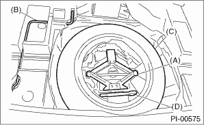
|
(A) |
Jack |
|
(B) |
Jack handle |
|
(C) |
Spare tire |
|
(D) |
Towing hook (Eye bolt) |
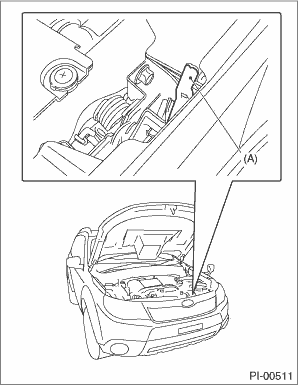
10. FRONT HOOD LOCK RELEASE SYSTEM
1. Operate the front hood release knob to check that the front hood will unlock properly.
2. Operate the lever (A) and check that the front hood is opened normally. Support the front hood with hood stay.
Check the battery terminals to make sure that there are no rust or corrosions due to fluid leaks. Check that the battery caps are securely tightened.
|
(A) |
Cap |
|
(B) |
Upper level |
|
(C) |
Lower level |
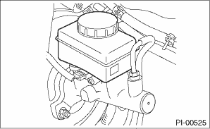
Check the brake fluid amount. If the amount is insufficient, carry out a brake line test to identify brake fluid leaks and check the brake operation. After that, refill the brake fluid tank with the specified type of fluid.
CAUTION:
If the brake fluid is spilt over exhaust pipe or the under cover, wipe it off with cloth to avoid emitting smoke or causing a fire.
CAUTION:
If the engine oil is spilt over exhaust pipe or the under cover, wipe it off with cloth to avoid emitting smoke or causing a fire.
1. Gasoline engine model
(1) Park the vehicle on a level surface.
(2) Remove the oil level gauge and wipe away the oil.
(3) Reinsert the oil level gauge all the way. Be sure that the oil level gauge is correctly inserted and properly orientated.
(4) Pull out the oil level gauge again, and check the oil level. If the engine oil level is below “L” line, add oil to bring the level up to “F” line.
(5) Start the engine and warm it up for a time.
(6) After turning off the engine, wait a few minutes for the oil to return to the oil pan before checking the oil level.
NOTE:
• Just after driving or while the engine is warm, engine oil level shows in the range between the “F” line and the notch mark. This is caused by thermal expansion of engine oil.
• To prevent overfilling of engine oil, do not add oil above “F” line when the engine is cold.
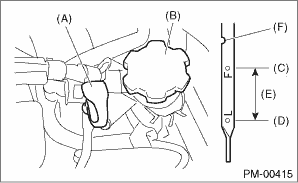
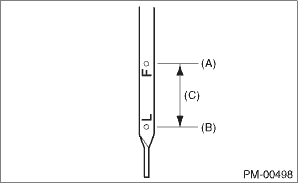
• Non-turbo engine model
|
(A) |
Engine oil level gauge |
|
(B) |
Engine oil filler cap |
|
(C) |
“F” line |
|
(D) |
“L” line |
|
(E) |
Approx. 1 L (1.1 US qt, 0.9 Imp qt) |
|
(F) |
Notch mark |
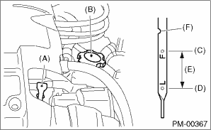
• Gasoline turbo model
|
(A) |
Oil level gauge |
|
(B) |
Engine oil filler cap |
|
(C) |
“F” line |
|
(D) |
“L” line |
|
(E) |
Approx. 1 L (1.1 US qt, 0.9 Imp qt) |
|
(F) |
Notch mark |
2. Diesel engine model
(1) Drive the vehicle for 5 — 10 km (3 — 6 miles) to raise the engine coolant temperature until the needle of the engine coolant temperature gauge goes up to the middle between Hot and Cold.
(2) Park the vehicle on a level surface.
(3) Stop the engine and leave it for five minutes.
(4) Remove the oil level gauge and wipe away the oil.
(5) Reinsert the oil level gauge all the way. Be sure that the oil level gauge is correctly inserted and properly orientated.
(6) Pull out the oil level gauge again, and check the oil level. If the engine oil level is below “L” line, add oil to bring the level up to “F” line.
(7) Drive the vehicle for 5 — 10 km (3 — 6 miles) to raise the engine coolant temperature until the needle of the engine coolant temperature gauge goes up to the middle between Hot and Cold.
(8) Park the vehicle on a level surface.
(9) Stop the engine and leave it for five minutes.
(10) Check the engine oil level.
NOTE:
• To prevent overfilling of engine oil, do not add oil above “F”.
|
(A) |
Oil level gauge |
|
(B) |
Engine oil filler cap |
|
(A) |
“F” line |
|
(B) |
“L” line |
|
(C) |
Approx. 1 L (1.1 US qt, 0.9 Imp qt) |
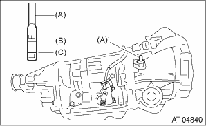
Check the transmission gear oil amount. If the amount of gear oil is inappropriate, check that no leaks are found. Then, add the necessary amount of the specified gear oil.
CAUTION:
If gear oil is spilt over the exhaust pipe, wipe it off with a cloth to avoid emitting smoke or causing a fire.
• 5MT gasoline engine model
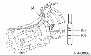
|
(A) |
Oil level gauge |
|
(B) |
Upper level |
|
(C) |
Lower level |
• 6MT diesel engine model
|
(A) |
Oil level gauge |
|
(B) |
Upper level |
|
(C) |
Lower level |
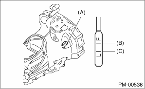
Check the AT front differential oil amount. If the amount of oil is inappropriate, check that no leaks are found. Then, add the necessary amount of the specified AT front differential oil.
CAUTION:
If gear oil is spilt over the exhaust pipe, wipe it off with a cloth to avoid emitting smoke or causing a fire.
|
(A) |
Oil level gauge |
|
(B) |
Upper level |
|
(C) |
Lower level |
Check the engine coolant amount on the reservoir. If the amount of engine coolant is insufficient, check that no leaks are found. Then, add the necessary amount of coolant with the specified concentration.
CAUTION:
If the coolant is spilt over exhaust pipe, wipe it off with cloth to avoid emitting smoke or causing a fire.
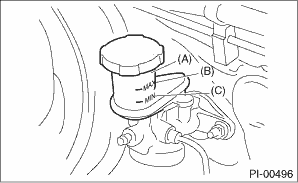
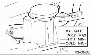
Check the clutch fluid amount. If the amount of fluid is insufficient, check that no leaks are found. Then, add the necessary amount of specified fluid.
|
(A) |
Reservoir tank |
|
(B) |
MAX. level |
|
(C) |
MIN. level |
CAUTION:
If any clutch fluid is spilt on the exhaust pipe, wipe it off with a cloth to avoid emitting smoke or causing a fire.
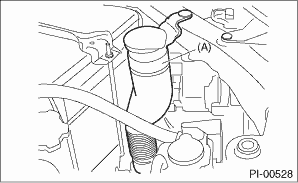
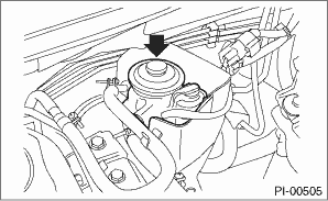
Check the window washer fluid amount. If the amount is insufficient, check that no leaks are found. Then, add the necessary amount of washer fluid.
|
(A) |
Window washer tank |
Close the front hood. Check that the front hood is completely latched.
Check the keyless entry system operations as follows:
1. Fully open all the door windows.
2. Remove the key from the ignition switch and close all the doors including rear gate.
3. Press the “ ” button on the keyless transmitter once. Check if all the doors are locked, and hazard light blinks once.
• Except for EK and ER
• For EK and ER
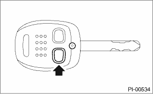
4. Press the “ ” button on the keyless transmitter once. Check if all the doors are unlocked, and hazard light blinks twice. (without model with double lock)
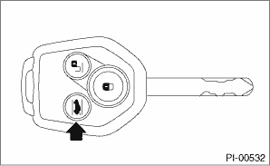
5. Press the “” button on the keyless transmitter once. Check if driver’s side door is unlocked, and hazard light blinks twice. Press the “” button second times are pushed from the first time within five seconds. Check if all the doors are unlocked, and hazard light blinks twice. (Model with double lock)
• Except for EK and ER
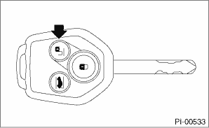
• For EK and ER
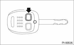
6. Close all the doors and rear gate, and press the “” button. Press the “”, then wait for 30 seconds. Check if all the doors and rear gate are locked automatically. (without model with double lock)
7. Press the rear gate open button once. Check if rear gate is unlocked, and hazard light blinks twice.
NOTE:
The following inspections show the initial settings. When the settings are different from the initial settings, use Subaru Select Monitor to check the details of each setting for inspections. 
• While carrying the access key, check that the room light illuminates when you move close to the front door handles of a vehicle in which all doors are locked.
• While carrying the access key, check that all doors unlock and lock, and the hazard lights flash when you press the door lock/unlock button or rear gate lock/unlock button.
NOTE:
• Rear gate unlocking means, when you press the rear gate opener button it can open the rear gate without access key.
• Rear gate locking means, when you press the rear gate opener button it can not open the rear gate without access key.
• The hazard lights flash twice when unlocking.
• The hazard lights flash once when locking.
• While carrying the access key, check that the all doors/rear gate are locked and the hazard lights flash once when you press the rear lock button.
• While carrying the access key, check that the rear gate unlocked with another doors and the hazard lights flash twice when you press the rear gate opener button of a vehicle in which all doors are locked.
• While rear gate is unlocking, check that the rear gate opens when the rear gate opener button is pressed whether you carry an access key or not.
|
(A) |
Rear lock button |
|
(B) |
Rear gate opener button |
• With all doors and the rear gate closed, and carrying the access key, check that all doors lock automatically 30 seconds after pressing the door request switch. (except model with double lock)
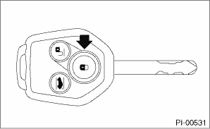
• Manually operate the access key button to check the lock/unlock of doors and rear gate, and the flashing of hazard lights.
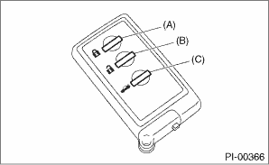
|
(A) |
LOCK button |
|
(B) |
OPEN button |
|
(C) |
Rear gate unlock button |
• Check the mechanical key attached to the access key can be used for locking/unlocking.
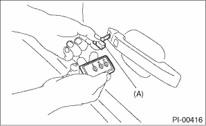
|
(A) |
Mechanical key |
• With the access key in the vehicle, check that warning buzzer sounds and locking does not occur when you press the door lock/unlock button or rear gate lock/unlock button (lock).
CAUTION:
Remove the mechanical key from the access key and hold the mechanical key.
• After the access key is carried into the vehicle while the engine is stopped, when the driver’s door glass is fully opened, and the LOCK button of the access key is pressed, the door is locked. Then check that the warning buzzer sounds and locking occurs. (Model with double lock)
CAUTION:
Check with the door glass fully opened.
Check that each seat provides full functionality in sliding and reclining. Check all of the functions of the rear seat.
Pull out the seat belt and then release it. Check that the belt retracts smoothly.
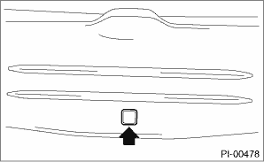
24. DELIVERY (TEST) MODE CONNECTOR
1. Turn the ignition switch to ON and check that the malfunction indicator light starts blinking.
2. If the light blinks, return the ignition key to LOCK.
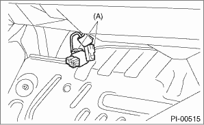
|
(A) |
Delivery (test) mode connector (green) |
3. Disconnect the delivery (test) mode connector under the passenger’s seat.
4. Then, turn the ignition key to ON again.
5. If the malfunction indicator light blinks even though the delivery (test) mode connector is disconnected, carry out an engine diagnosis.
6. Insert the disconnected test mode connector into the backside of the ECM protector.
|
(A) |
Delivery (test) mode connector |
|
(B) |
ECM protector |
1. Check if all keys of the vehicle can start the engine.
2. 60 seconds after turning the ignition switch from ON to ACC or OFF, or immediately after removing the key, check if the security indicator light blinks.
NOTE:
If malfunctions occur, refer to “IMMOBILIZER (DIAGNOSIS)”.
Start the engine and check that the engine starts smoothly. If the battery voltage is low, recharge or replace the battery. If any noises are observed, immediately stop the engine and check and repair the abnormal components.
NOTE:
For diesel engine model, if the vehicle is out of gas and the engine does not start, after fuel supply, press the priming pump until it can not be pressed further, and then start the engine again.
Listen to the exhaust noise to see if no noises and leaks are observed. Check if there is no exhaust leakage.
28. INDICATOR AND WARNING LIGHTS
Check that all indicator lights and warning lights operate normally.
Operate the heater & ventilation system to check for normal airflow outlet control, air inlet control, airflow capacity and heating performance.
Operate the air conditioner. Check that the A/C compressor operates normally and enough cooling is provided.
NOTE:
Idle the engine and operate the air conditioner for 5 minutes to prevent insufficient lubrication of air conditioner system.
Check the clock for normal operations and enough accuracy.
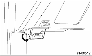
Install the antenna.
1. Remove the cap from the antenna base.
2. Tighten the antenna rod on the rear seat by hand in the direction indicated by the arrow to install.
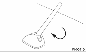
3. Make sure that radio reception operates correctly after installation.
Check the radio for full functionality and normal noise level. Check the CD player and AUX operations.
1. Check all display functions for normal operation. (Refer to operating manuals for operation procedures.)
2. Check the map disc (DVD) are provided on vehicle.
3. Check that the navigation system operates normally.
35. FRONT ACCESSORY POWER SUPPLY SOCKET
Check the operation of the front accessory power supply socket.
1. Check the headlight operations.
2. Check the stop light operation.
3. For model with manual headlight beam levelizer, check the operation of headlight beam levelizer.
4. Check other lights for normal operations.
Check that the illumination control operates normally.
Check that the window washer system injects washer fluid to the specified area of the windshield shown in the figure.
Front injection position:
A: 265 mm (10.43 in)
B: 117 mm (4.61 in)
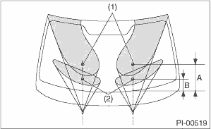
|
(1) |
Upper side injection center hitting position |
|
(2) |
Lower side injection center hitting position |
Rear injection position:
A: 37 mm (1.46 in)
B: 72°
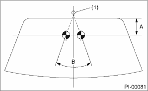
|
(1) |
Nozzle |
For model with headlight washers, turn the ignition switch and the headlights ON. Check that the headlight washers operate when the front wiper washer switch has been ON for 0.6 seconds (approximately 1 second).
NOTE:
The headlight washers stop operation within 0.6 seconds of the front wiper washer switch being turned OFF.
Check the front and rear wipers for normal operations.
Check that the wiper deicer operates normally.
Operate the power window switches one by one to check that each of the power windows goes up and down without noises.
Check that the remote control mirror operates normally.
Check the foot brake for normal operations.
Check the parking brake for normal operations.
When pulling the parking brake with a force of 196 N (20 kgf, 44 lbf), check that the lever stroke of parking brake lever is 7 — 8 notches.
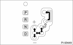
1. Turn the ignition switch to ON.
2. While brake pedal is not depressed, check if the select lever does not move from “P” range.
3. While brake pedal is depressed, check if the select lever moves from “P” range.
4. Set the select lever to other than “P” range.
5. When the ignition switch is turned OFF, check if the ignition key switch cannot be removed.
6. Set the AT selector lever to each gear position and check the shifting while driving the vehicle.
|
Selector position |
Gear position | |||
|
1st |
2nd |
3rd |
4th | |
|
D |
OK |
OK |
OK |
OK |
|
SPORT shift |
OK |
OK |
OK |
OK |
Operate the cruise control system. Check that the system is activated and deactivated correctly.
After selecting all positions (P, R, N, D), set the select lever in “P” range. Idle the engine for 1 to 2 minutes, and measure the ATF level. If the amount is insufficient, check that no leaks are found. Then, add the necessary amount of the specified ATF.
CAUTION:
If the ATF is spilt over exhaust pipe, wipe it off with cloth to avoid emitting smoke or causing a fire.
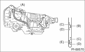
|
(A) |
Level gauge |
|
(B) |
Check position when “HOT” [70 to 80°C (158 to 176°F)] |
|
(C) |
Upper level |
|
(D) |
Lower level |
|
(E) |
Check position when “COLD” [20 to 30°C (68 to 86°F)] |
• For the hydraulic power steering model, check that the power steering fluid level is normal. If insufficient, check for leaks. Then add the necessary amount of the specified power steering fluid.
CAUTION:
If any power steering fluid is spilt over the exhaust pipe, wipe it off with a cloth to avoid emitting smoke or causing a fire.
• For electric power steering model, check the when the ignition switch to ON illuminates “STEERING”, after starting engine “STEERING” is turn off.
Check entire areas of the vehicle for any trace of coolant/oil/fluid leaks.
Spray the vehicle with water using a hose and check that no water enters the passenger compartment.
• Before performing the water leakage test, remove anything that may obstruct the operation or which must be kept dry.
• Close all the windows and doors securely. Close the front hood before starting the test.
• Connect a hose to a tap, and spray water on the vehicle. The rate of water spray must be approx. 20 to 25 L (5.3 — 6.6 US gal, 4.4 — 5.5 Imp gal) per minute.
When spraying water on areas adjacent to the floor and wheel house, increase the pressure. When spraying water on areas other than the floor and wheel house, decrease the pressure. But the force of water must be made strong occasionally by pressing the end of the hose.
NOTE:
Be sure to keep the hose at least 10 cm (3.9 in) away from vehicle.
Check the following areas.
• Front window and body framework mating portion
• Door mating portions
• Glass mating portions
• Rear quarter window mating portions
• Rear window and body framework mating portion
• Around roof drips
If any dampness in the compartments is discovered after the water has been applied, carefully check all the areas that may have possibly contributed to the leak.
1. When vehicle body is covered with protective film (wrap guard), peel it off.
NOTE:
• It is easier to remove the wrap guard using steam.
• For the vehicle left for a long time or at low temperature, sprinkle some water heated 50 — 60°C (122 — 140°F) over the vehicle to raise its surface temperature before peeling off the wrap guard. Do not use the water heated to over 60°C (140°F).
• If the adhesive remains exists on the coated surface, soak a flannel rag, etc. with a small amount of coating wax or solvent such as oil benzene and IPA, put the soaked cloth on the remains lightly, and then wipe them off with a flannel rag etc.
• Keep solvent from touching the resin or rubber parts. Do not use coating wax or solvent while the component surface temperature is high due to hot weather etc.
• If the coated surface is swollen out due to seams or moisture, expose the vehicle to the sunlight for a few hours or heat the seam and swollen portions using a dryer etc.
• Dispose of the peeled wrap guard as burnable industrial garbage.
2. Check the whole vehicle body for flaking paint, damage by transportation, corrosion, dirt, cracks or blisters.
NOTE:
• It is better to determine an inspection pattern in order to avoid missing an area, since the total inspection area is wide.
• Do not repair the body paint unless absolutely necessary. Also, if the vehicle is in need of repair to remove scratches or corroded paint, the repair area must be limited to the minimum. Re-painting and spray painting must be avoided as much as possible.
3. Check each window glass for scratches carefully. Slight damage may be removed by polishing with cerium oxide. (Fill a cup half with cerium oxide, and add warm water to it. Then agitate the content until it turns to wax. Apply this wax to a soft cloth, and polish the glass with it.)
4. Check each portion of the vehicle body and underside components for the formation of rust. If rust is discovered, remove it with sandpaper of #80 to #180 and treat the surface with rust preventive. After this treatment is completed, flush the portion thoroughly, and prepare the surface for repair painting.
5. Check each portion of body and all of the exterior parts for deformation or distortion. Also, check each light lens for cracks.