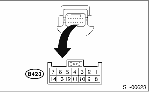
1. Disconnect the push button ignition switch connector.
2. Measure between terminals using a tester, or connect the battery and check indicator operation.
|
Terminal No. |
Standard |
Measuring condition |
Item |
|
4 (COM) ←→ 5 (GND) |
Continuity exists |
Always |
Continuity |
|
7 (SSW1) ←→ 5 (GND) |
Continuity exists |
Push button ignition switch released → pressed |
Continuity |
|
2 (SSW2) ←→ 5 (GND) |
Continuity exists |
Push button ignition switch released → pressed |
Continuity |
|
11 (SWIL) ←→ 5 (GND) |
Goes off → Red switch illumination light |
Battery voltage applied between terminals 11 (+) ←→ 4 (−) |
Operation |
|
12 (INDS) ←→ 5 (GND) |
Turns off → Switch indicator lights in green |
Battery voltage applied between terminals 12 (+) ←→ 4 (−) |
Operation |
|
13 (INDW) ←→ 5 (GND) |
Turns off → Switch indicator lights in orange |
Battery voltage applied between terminals 13 (+) ←→ 4 (−) |
Operation |
NOTE:
Replace the push button ignition switch if faulty.