1. Clean all the disassembled parts, and check for wear, damage or any other faults, then repair or replace as necessary.
2. When disassembling, check the inside of gearbox for water. If any water is found, carefully check the boot for damage, input shaft dust seal, adjusting screw and boot clips for poor sealing. If faulty, replace with new parts.
|
No. |
Parts |
Inspection |
Corrective action |
|
1 |
Input shaft |
(1) Bent input shaft (2) Damage on serration |
If the bend or damage is excessive, replace the entire gearbox. |
|
2 |
Dust seal |
(1) Crack or damage (2) Wear |
If the outer wall slips, the lip is worn out or damage is found, replace it with a new part. |
|
3 |
Rack & pinion |
Poor mating of rack with pinion |
(1) Adjust the backlash properly. By measuring the turning torque of the gearbox and sliding resistance of rack, check if the rack & pinion engage uniformly and smoothly with each other. (Refer to “Service limit”.) (2) Pull out the entire rack to allow viewing of the teeth, and check for damage. When abnormality is found in either (1) or (2), replace the entire gearbox. |
|
4 |
Gearbox unit |
(1) Bending of the rack shaft (2) Bending of the cylinder portion (3) Crack or damage on the cast iron portion |
Replace the gearbox with a new part. |
|
(4) Wear or damage on rack bushing |
If the free play of rack shaft in radial direction is out of the specified range, replace the gearbox with new part. (Refer to “Service limit”.) | ||
|
(5) Wear on input shaft bearing |
If the free play of input shaft in radial and axial direction is out of the specified range, replace the gearbox with a new part. (Refer to “Service limit”.) | ||
|
5 |
Boot |
Crack, damage or deterioration |
Replace. |
|
6 |
Tie-rod |
(1) Looseness of ball joint (2) Bend of tie-rod |
Replace. |
|
7 |
Tie-rod end |
Damage or deterioration of dust seal |
Replace. |
|
8 |
Adjusting screw spring |
Deterioration |
Replace. |
|
9 |
Boot clip |
Deterioration |
Replace. |
|
10 |
Sleeve |
Damage |
Replace. |
|
11 |
Pipe |
(1) Damage to flared surface (2) Damage to flare nut (3) Damage to pipe |
Replace. |
Make a measurements as follows. If it exceeds the specified service limits, adjust or replace.
NOTE:
When making a measurement, vise the gearbox using ST. Never vise the gearbox by inserting aluminum plates etc. between vise and gearbox.
| ST1 926200000 | STAND |
| ST2 34199AG000 | BOSS D |
Rack shaft sliding resistance:
Service limit
314 N (32 kgf, 71 lbf) or less
Left/right differential of sliding resistance:
20% or less
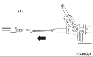
|
(1) |
Right-turn steering |
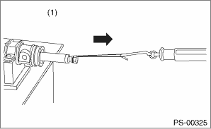
|
(1) |
Left-turn steering |
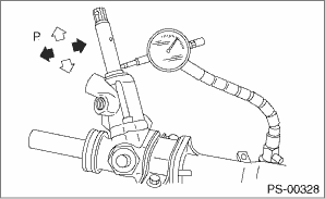
3. RACK SHAFT PLAY IN THE RADIAL DIRECTION
Right-turn steering:
Service limit
Direction 

0.4 mm (0.016 in) or less
Direction 

0.6 mm (0.024 in) or less
Condition
L: 5 mm (0.20 in)
P: 98 N (10 kgf, 22 lbf)
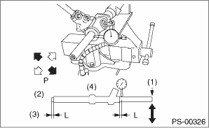
|
(1) |
Under the step |
|
(2) |
Right-turn steering |
|
(3) |
Measuring point |
|
(4) |
Right |
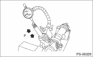
Left-turn steering:
Service limit
Direction
0.4 mm (0.016 in) or less
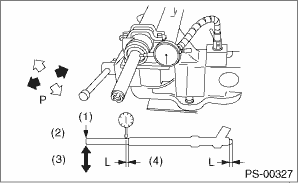
|
(1) |
Under the step |
|
(2) |
Left-turn steering |
|
(3) |
Measuring point |
|
(4) |
Left |
In radial direction:
Service limit
0.18 mm (0.0071 in) or less
Condition
P: 98 N (10 kgf, 22 lbf)
In axial direction:
Service limit
0.27 mm (0.0106 in) or less
Condition
P: 20 — 49 N (2 — 5 kgf, 4 — 11 lbf)
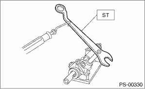
5. TURNING RESISTANCE OF GEARBOX
Using the ST, measure the gearbox turning resistance.
| ST 34099PA100 | SPANNER |
Service limit:
Maximum allowable resistance:
13 N (1.3 kgf, 9.6 lbf) or less
Difference between right and left turning resistance:
20% or less
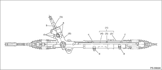
|
(1) |
Power cylinder |
(3) |
Rack piston |
(5) |
Input shaft |
|
(2) |
Cylinder |
(4) |
Rack axle |
(6) |
Valve housing |
1. Lift up the vehicle.
2. If a fluid leak is found, clean the fluid completely from the suspect area, and turn the steering wheel 30 to 40 times to the left and right from lock to lock, with the engine running, and check again for leaks immediately, and also after a few hours have passed.
3. Cause and solution for oil leakage from “a”
The oil seal is damaged. Replace the valve assembly with a new part.
4. Cause and measure for oil leakage from “b”.
The torsion bar O-ring is damaged. Replace the valve assembly with a new part.
5. Cause and measure for oil leakage from “c”.
The oil seal is damaged. Replace the oil seal.
6. Cause and solution for oil leakage from “d”.
The pipe is damaged. Replace the faulty pipe or O-ring.