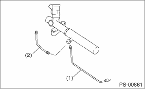
1. Disconnect the pipes A and B from steering body and control valve housing.
|
(1) |
Pipe A |
|
(2) |
Pipe B |
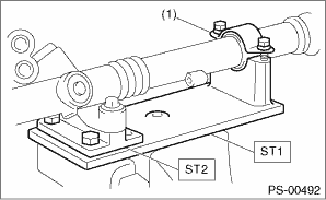
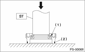
2. Secure the gearbox removed from vehicle in a vise using ST.
| ST1 926200000 | STAND |
| ST2 34199AG000 | BOSS D |
CAUTION:
Using the ST, affix the gearbox assembly to a vice as shown in the figure. Do not hold the gearbox on the vice without this ST.
|
(1) |
Clamp |
3. Remove the tie-rod end and lock nut from the gearbox.
4. Remove the clip on the outer side of the boot, and move the boot towards the tie-rod end.
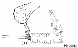
|
(1) |
Clip |
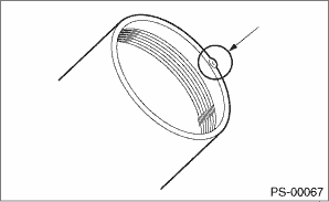
5. Using a flat tip screwdriver, remove the band from boot.
NOTE:
Replace the boot if there is damage, cracks or deterioration.
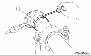
|
(1) |
Band |
6. Using the ST, loosen the lock nut.
| ST 926230000 | SPANNER |
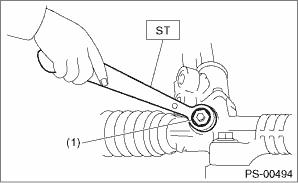
|
(1) |
Lock nut |
7. Tighten the adjusting screw until it can no longer be tightened.
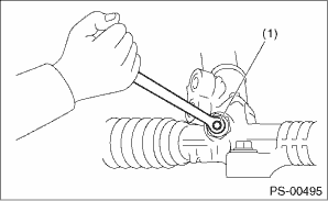
|
(1) |
Adjusting screw |
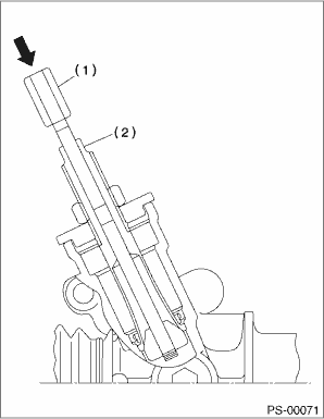
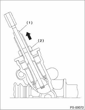
8. Remove the tie-rod.
9. Loosen the adjusting screw, and remove the spring and sleeve.
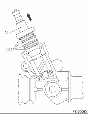
10. Remove any soil on the input shaft. Being careful not to damage the housing and input shaft, and that no foreign objects enter the gearbox, pull out the dust cover.
CAUTION:
Wrap tape around the input shaft splines to prevent damaging the dust cover.
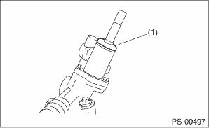
|
(1) |
Dust cover |
11. Match the pin of the ST to the plug hole and attach. Turn the ST counterclockwise to remove the plug.
| ST 34199AE090 | PLUG WRENCH |
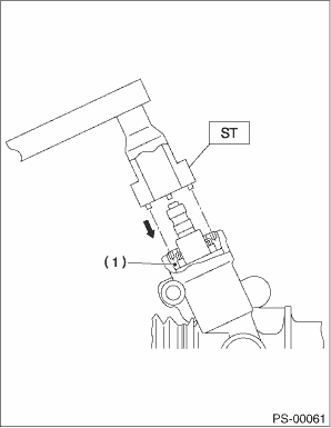
|
(1) |
Plug |
12. Remove the valve assembly while being careful not to damage the seal rings and valve housing inner surfaces.
|
(1) |
Valve assembly |
|
(2) |
Seal ring |
13. Remove the holder.
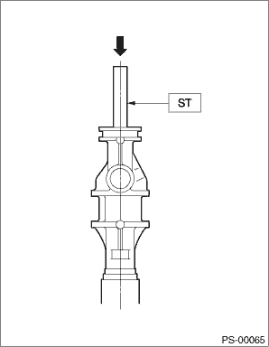
14. Attach the ST to the rack pinion housing side, and push the rack out together with the outer side oil seal.
| ST 34199FE000 | INSTALLER & REMOVER |
NOTE:
Plug the pipe connection of the steering body, so that fluid will not come pouring out.
|
(1) |
Rack piston |
|
(2) |
Outer side oil seal |
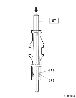
15. Insert the ST from the valve side, and push out the backup ring and oil seal.
| ST 34199FE010 | REMOVER |
16. Correct the crimped area of the cylinder using ST1 and ST2.
| ST1 34099FA080 | PUNCH |
| ST2 34199FE020 | BASE |
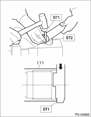
|
(1) |
Cylinder |
17. If the cylinder end is deformed to form a protrusion, use an oil stone to correct.
18. Using the ST, remove the oil seal and push out from the plug.
| ST 34199AE100 | OIL SEAL PLUG REMOVER |
NOTE:
Do not apply a force to the end surface of a plug.
|
(1) |
Oil seal |
|
(2) |
O-ring |
19. Set the ST at the dimensions indicated in the figure.
| ST 34199AE120 | GEARBOX OIL SEAL REMOVER |
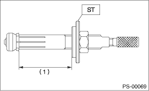
|
(1) |
70 mm (2.76 in) |
20. Set the stopper in the gearbox body first, then insert the tip of the ST into the gearbox body.
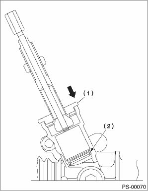
|
(1) |
Stopper |
|
(2) |
Oil seal |
21. Fix the width across flats in place, push in while rotating the rod, and hook the oil seal.
|
(1) |
Rod |
|
(2) |
Width across flats |
22. Fix the width across flats in place, turn the nut and pull out the oil seal.
CAUTION:
Be careful not to damage the inner surface of the gearbox.
|
(1) |
Width across flats |
|
(2) |
Nut |