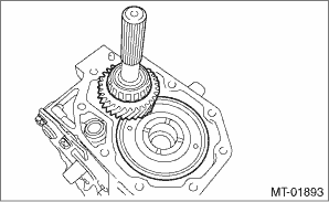
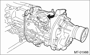
1. Install the center differential and transfer driven gear into the transfer case.
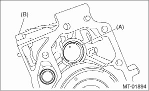
2. Remove the bearing outer race from the extension case.
|
(A) |
Bearing outer race |
|
(B) |
Extension case |
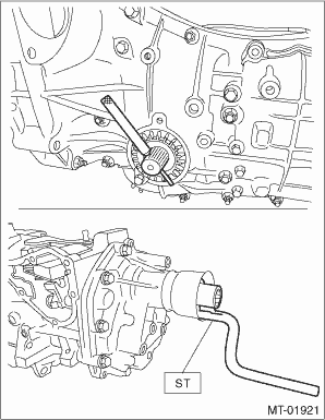
3. While pressing the bearing outer race horizontally, rotate the driven shaft for ten turns.
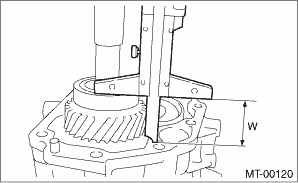
4. Measure the height “W” between transfer case and taper roller bearing on the transfer driven gear.
|
W |
Measured value |
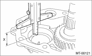
5. Measure depth “X” on bearing insertion part of the extension case.
NOTE:
Measure with bearing outer race and thrust washer removed.
|
X |
Measured value |
6. Calculate the thrust washer thickness “t” using the following calculation.
t = X − W + (0.15 — 0.2 mm (0.006 — 0.008 in))
7. Select the washer with the nearest value in the following table.
Preload (amount of standard protrusion) of the taper roller bearing:
0.15 — 0.2 mm (0.006 — 0.008 in)
NOTE:
Be sure that it is always within the preload.
|
Thrust washer (50 × 61 × t) | |
|
Part No. |
Thickness mm (in) |
|
803050060 |
0.50 (0.0197) |
|
803050061 |
0.55 (0.0217) |
|
803050062 |
0.60 (0.0236) |
|
803050063 |
0.65 (0.0256) |
|
803050064 |
0.70 (0.0276) |
|
803050065 |
0.75 (0.0295) |
|
803050066 |
0.80 (0.0315) |
|
803050067 |
0.85 (0.0335) |
|
803050068 |
0.90 (0.0354) |
|
803050069 |
0.95 (0.0374) |
|
803050070 |
1.00 (0.0394) |
|
803050071 |
1.05 (0.0413) |
|
803050072 |
1.10 (0.0433) |
|
803050073 |
1.15 (0.0453) |
|
803050074 |
1.20 (0.0472) |
|
803050075 |
1.25 (0.0492) |
|
803050076 |
1.30 (0.0512) |
|
803050077 |
1.35 (0.0531) |
|
803050078 |
1.40 (0.0551) |
|
803050079 |
1.45 (0.0571) |
8. Fit the thrust washers on the transfer drive shaft.
9. Install the bearing outer race into the extension case.
10. Measure the depth “S” between transfer case and center differential.
| ST 398643600 | GAUGE |
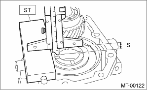
|
S |
Measured value |
11. Measure the height “T” between the extension case and transfer drive gear.
| ST 398643600 | GAUGE |
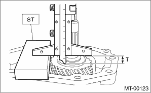
|
T |
Measured value |
NOTE:
Thickness of ST: 15 mm (0.59 in)
12. Calculate the thrust washer thickness “U” using the following calculation.
U = S + T − 30 mm (1.18 in) [Thickness of ST]
13. Select a suitable washer in the following table.
Standard clearance:
0.15 — 0.35 mm (0.0059 — 0.0138 in)
|
Thrust washer | |
|
Part No. |
Thickness mm (in) |
|
803036050 |
0.9 (0.035) |
|
803036054 |
1.0 (0.039) |
|
803036051 |
1.1 (0.043) |
|
803036055 |
1.2 (0.047) |
|
803036052 |
1.3 (0.051) |
|
803036056 |
1.4 (0.055) |
|
803036053 |
1.5 (0.059) |
|
803036057 |
1.6 (0.063) |
|
803036058 |
1.7 (0.067) |
|
803036080 |
1.8 (0.071) |
|
803036081 |
1.9 (0.075) |
14. Fit the thrust washer onto the center differential.
15. Apply a proper amount of liquid gasket to the transfer case mating surface.
Liquid gasket:
THREE BOND 1215 (Part No. 004403007) or equivalent
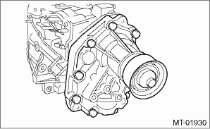
16. Install the extension case assembly to the transfer case.
Tightening torque:
40 N·m (4.1 kgf-m, 29.5 ft-lb)
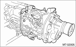
17. Install the extension case assembly along with the transfer case to the transmission case.
(1) Insert the axle shaft and hold, then move the HANDLE to align the spline position to install.
| ST 18631AA000 | HANDLE |
| Part No. 38415AA100 | AXLE SHAFT |
NOTE:
Push the transfer case assembly until the knock pin protrudes slightly from the transfer case.
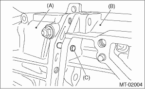
|
(A) |
Transmission case |
|
(B) |
Transfer case |
|
(C) |
Knock pin |
(2) Select the 1st-2nd side of selector lever, then install it so that the shifter arm edge and fork rod does not contact.
18. Temporarily tighten the transfer case assembly.
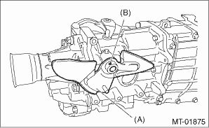
19. Install the shift lever COMPL to the shifter arm No. 2, then insert the remover or similar tool instead of spring pin.
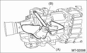
|
(A) |
Shift lever COMPL |
|
(B) |
Remover |
20. Operate the selector arm and remover to confirm the correct shifting into each gear is possible.
21. Tighten the transfer case assembly to the specified torque.
Tightening torque:
24.5 N·m (2.5 kgf-m, 18.1 ft-lb)
22. Install the shift lever COMPL to the shifter arm No. 2, then fix it using new spring pin.
|
(A) |
Shift lever COMPL |
|
(B) |
Spring pin |
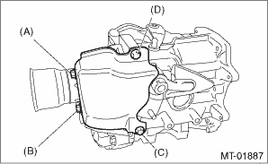
23. Install the transfer cover.
(1) Temporarily tighten the transfer cover mounting bolts.
(2) Tighten bolts in order of (B), (A), (C), (D) to the specified torque.
Tightening torque:
15 N·m (1.5 kgf-m, 11.1 ft-lb)
24. Install the transmission cover. 