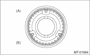
1. Install the sleeve and the gear & hub assembly by matching the alignment marks.
NOTE:
• Position the open ends of the spring 120° apart.
• Use the new gear & hub assembly, if replacing the gear or hub.
|
(A) |
1st-2nd sleeve & hub ASSY |
|
(B) |
1st gear side |
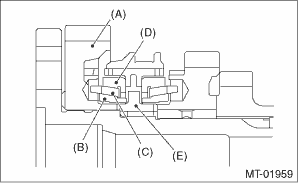
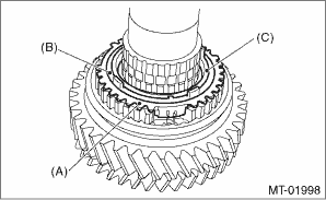
2. Install the 1st driven gear, inner baulk ring, synchro cone and outer baulk ring and 1st-2nd synchronizer hub onto driven shaft.
NOTE:
• Take care to install the gear & hub assembly in proper direction.
• Align the baulk ring and gear and hub assembly with the key groove.
|
(A) |
1st driven gear |
|
(B) |
Inner baulk ring |
|
(C) |
Synchro cone |
|
(D) |
Outer baulk ring |
|
(E) |
1st-2nd synchronizer hub |
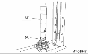
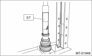
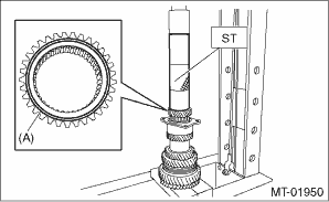
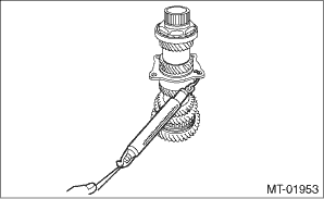
3. Install the 2nd driven gear bushing onto driven shaft using ST and a press.
CAUTION:
Do not apply a load in excess of 10 kN (1 ton, 1.1 US ton, 1.0 Imp ton).
NOTE:
• Attach a cloth to the end of the driven shaft to prevent damage.
• When press fitting, align the oil holes of the shaft and bushing
| ST 18654AA000 | INSTALLER |
|
(A) |
2nd driven gear bushing |
4. Attach the 1st-2nd coupling sleeve and 1st-2nd shifting insert key to the driven shaft.
NOTE:
• Install the 1st-2nd coupling sleeve with the long flange side facing the 1st driven gear.
• Install the 1st-2nd shifting insert keys at 120° interval positions.
|
(A) |
1st-2nd coupling sleeve |
|
(B) |
1st-2nd shifting insert key (three positions) |
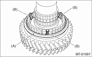
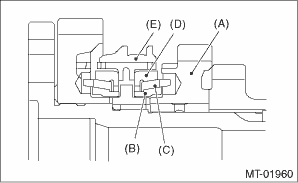
5. Install the outer baulk ring, synchro cone, inner baulk ring and 2nd driven gear to driven shaft.
|
(A) |
Outer baulk ring |
|
(B) |
Synchro cone |
|
(C) |
Inner baulk ring |
|
(A) |
2nd driven gear |
|
(B) |
Inner baulk ring |
|
(C) |
Synchro cone |
|
(D) |
Outer baulk ring |
|
(E) |
1st-2nd coupling sleeve |
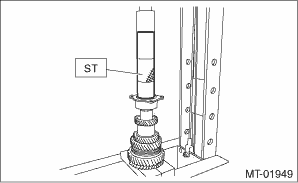
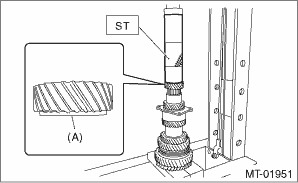
6. After installing key on driven shaft, install the 3rd-4th driven gear using an ST and a press.
CAUTION:
Do not apply a load in excess of 10 kN (1 ton, 1.1 US ton, 1.0 Imp ton).
NOTE:
Align the groove in baulk ring with the insert.
| ST 499277200 | INSTALLER |
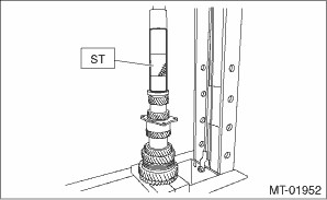
7. Install a set of roller bearings onto the driven shaft using ST and a press.
CAUTION:
Do not apply a load in excess of 10 kN (1 ton, 1.1 US ton, 1.0 Imp ton).
| ST 499277200 | INSTALLER |
8. Install the 5th driven gear onto driven shaft using ST and a press.
CAUTION:
Do not apply a load in excess of 10 kN (1 ton, 1.1 US ton, 1.0 Imp ton).
NOTE:
Install the 5th driven gear with the groove side facing the 6th driven gear.
| ST 499277200 | INSTALLER |
|
(A) |
Install with the groove side facing the 6th driven gear. |
9. Install the drive pinion spacer to driven shaft, then install the 6th driven gear to driven shaft using the ST and a press.
CAUTION:
Do not apply a load in excess of 10 kN (1 ton, 1.1 US ton, 1.0 Imp ton).
NOTE:
Install the 6th driven gear with the stepped side facing the 5th driven gear.
| ST 499277200 | INSTALLER |
|
(A) |
Install with the stepped side facing the 5th driven gear. |
10. Install the ball bearing onto driven shaft using ST and a press.
CAUTION:
Do not apply a load in excess of 10 kN (1 ton, 1.1 US ton, 1.0 Imp ton).
| ST 499277200 | INSTALLER |
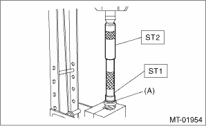
11. Tighten the new lock nuts to the specified torque using ST1 and ST2.
| ST1 499987300 | SOCKET WRENCH (50) |
| ST2 18680AA020 | HOLDER |
Tightening torque:
440 N·m (44.9 kgf-m, 324.5 ft-lb)
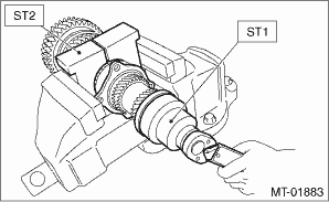
NOTE:
• Crimp the locknut in 2 locations.
• Using a spring scale, check that starting torque of the roller bearing is 0.1 to 1.5 N (0.01 to 0.15 kgf, 0.02 to 0.34 lbf).
12. Install the roller bearing onto drive pinion.
NOTE:
When installing the roller bearing, note its directions (front and rear) because the knock pin hole of outer race is offset.
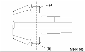
|
(A) |
Roller bearing |
|
(B) |
Knock pin hole |
13. Install the washer using ST1, ST2 and a press.
CAUTION:
Do not apply a load in excess of 10 kN (1 ton, 1.1 US ton, 1.0 Imp ton).
| ST1 499277100 | BUSHING 1-2 INSTALLER |
| ST2 499277200 | INSTALLER |
|
(A) |
Washer |
14. Install the thrust bearing and needle bearing. Install the driven shaft assembly.
15. Install the drive pinion collar, needle bearing, adjusting washer No. 2, thrust bearing, adjusting washer No. 1 and differential bevel gear sleeve in this order.
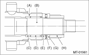
|
(A) |
Driven shaft |
|
(B) |
Drive pinion shaft |
|
(C) |
Drive pinion collar |
|
(D) |
Needle bearing (25 × 30 × 20) |
|
(E) |
Adjusting washer No. 2 (25 × 36 × t) |
|
(F) |
Thrust bearing (25 × 36 × 2) |
|
(G) |
Adjusting washer No. 1 (25 × 36 × t) |
|
(H) |
Differential bevel gear sleeve |
16. Adjust the thrust bearing preload. 