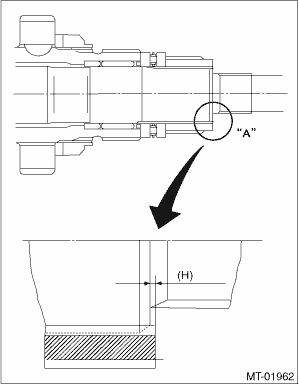
1. Select a suitable adjusting washer No. 1 so that dimension (H) will be zero in a visual check. Position the washer (20 × 31 × 4) and lock washer (20 × 31 × 2.3) and attach the lock nut (20 × 11).
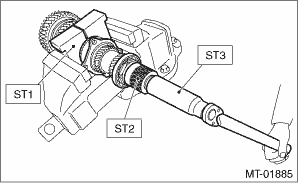
2. Using the ST1, ST2 and ST3, tighten the new lock nut to the specified torque.
| ST1 18680AA020 | HOLDER |
| ST2 18667AA020 | HOLDER |
| ST3 18662AA010 | SOCKET (27) |
Tightening torque:
126 N·m (12.8 kgf-m, 92.9 ft-lb)
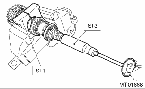
3. After removing the ST2 used in step 2), measure the starting torque using torque driver.
| ST1 18680AA020 | HOLDER |
| ST3 18662AA010 | SOCKET (27) |
Starting torque:
0.3 — 0.8 N·m (0.03 — 0.08 kgf-m, 0.2 — 0.6 ft-lb)
4. If the starting torque is not within the specified limit, select new adjusting washer No. 1 and recheck starting torque.
|
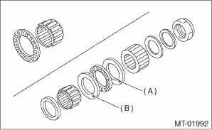
(A) |
Adjusting washer No. 1 |
|
(B) |
Adjusting washer No. 2 |
|
Adjusting washer No. 1 | |
|
Part No. |
Thickness mm (in) |
|
803025071 |
2.925 (0.1152) |
|
803025072 |
2.950 (0.1161) |
|
803025073 |
2.975 (0.1171) |
|
803025074 |
3.000 (0.1181) |
|
803025075 |
3.025 (0.1191) |
|
803025076 |
3.050 (0.1201) |
|
803025077 |
3.075 (0.1211) |
5. If the specified starting torque cannot be obtained by the selection of washer No. 1, select adjusting washer No. 2 from the list below. Repeat steps 1) through 4) to adjust starting torque.
|
(A) |
Adjusting washer No. 1 |
|
(B) |
Adjusting washer No. 2 |
|
Starting torque |
Dimension H |
Adjusting washer No. 2 |
|
Low |
Small |
Select thicker one. |
|
High |
Large |
Select thinner one. |
|
Adjusting washer No. 2 | |
|
Part No. |
Thickness mm (in) |
|
803025070 |
2.850 (0.1122) |
|
803025074 |
3.000 (0.1181) |
|
803025078 |
3.150 (0.1240) |
6. Recheck that the starting torque is within the specified range, then crimp the lock nut at four positions.