1. CLUTCH SWITCH (CRUISE CONTROL)
1. Move the clevis pin of push rod to left and right, retain it at the position where it moves smoothly, and measure the clutch pedal stroke.
Clutch pedal full stroke A:
130 — 135 mm (5.12 — 5.31 in) (gasoline non-turbo model)
135 — 140 mm (5.31 — 5.51 in) (gasoline turbo and diesel turbo model)
Tightening torque:
T: 8 N·m (0.8 kgf-m, 5.9 ft-lb)
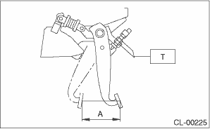
2. If the clutch pedal stroke is out of specification, adjust the stroke. 
3. Connect the clutch switch connector.
2. CLUTCH SWITCH (CLUTCH START)
• LHD model
1. Fully depress the clutch pedal and hold it.
2. Install the clutch pedal plate and clutch switch so that the gap between them is 3.1 — 4.1 mm (0.12 — 0.16 in), and then tighten the lock nut.
Tightening torque:
8 N·m (0.8 kgf-m, 5.9 ft-lb)
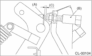
|
(A) |
Plate |
|
(B) |
Clutch switch |
|
(C) |
3.1 — 4.1 mm (0.12 — 0.16 in) |
3. Connect the clutch switch connector.
4. Make sure that engine does not start with clutch pedal not depressed.
5. Make sure that engine starts with clutch pedal fully depressed.
• RHD model
1. Fully depress the clutch pedal and hold it.
2. Install the clutch pedal plate and clutch pedal so that the gap between them is 3.1 — 4.1 mm (0.12 — 0.16 in), and then tighten the lock nut.
Tightening torque:
8 N·m (0.8 kgf-m, 5.9 ft-lb)
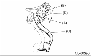
|
(A) |
3.1 — 4.1 mm (0.12 — 0.16 in) |
|
(B) |
Clutch switch (clutch start) |
|
(C) |
Clutch pedal |
|
(D) |
Lock nut |
3. Connect the clutch switch connector.
4. Make sure that engine does not start with clutch pedal not depressed.
5. Make sure that engine starts with clutch pedal fully depressed.