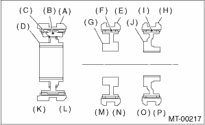
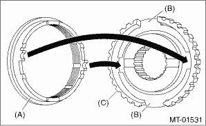
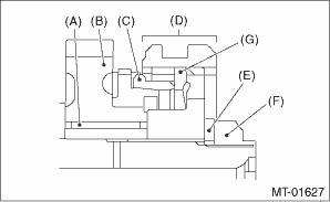
1. When the sleeve & hub assemblies have been disassembled, reassemble by aligning the alignment marks.
NOTE:
Position the spring opening of the hub assembly and the high-low sleeve at a position spaced apart by 120°.
|
(A) |
High-low coupling sleeve |
|
(B) |
Shifting insert |
|
(C) |
High-low synchronizer spring |
|
(D) |
High-low synchronizer hub |
|
(E) |
Sleeve |
|
(F) |
Insert key |
|
(G) |
3rd-4th synchronizer hub |
|
(H) |
Sleeve |
|
(I) |
Insert key |
|
(J) |
5th reverse synchronizer hub |
|
(K) |
High side |
|
(L) |
Low side |
|
(M) |
3rd side |
|
(N) |
4th side |
|
(O) |
5th side |
|
(P) |
Reverse side |
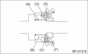
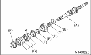
2. Install the 3rd drive gear, outer baulk ring, synchro cone, inner baulk ring, sleeve & hub assembly for the 3rd needle bearing, on the transmission main shaft.
NOTE:
Align the groove in baulk ring with the shifting insert.
|
(A) |
3rd needle bearing |
|
(B) |
3rd drive gear |
|
(C) |
Inner baulk ring |
|
(D) |
Synchro cone |
|
(E) |
Outer baulk ring |
|
(F) |
Sleeve & hub ASSY |
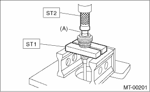
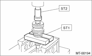
3. Install the 4th needle bearing race onto transmission main shaft using ST1, ST2 and press.
CAUTION:
Do not apply a load in excess of 10 kN (1 ton, 1.1 US ton, 1.0 Imp ton).
| ST1 899714110 | REMOVER |
| ST2 499877000 | RACE 4-5 INSTALLER |
|
(A) |
4th needle bearing race |
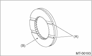
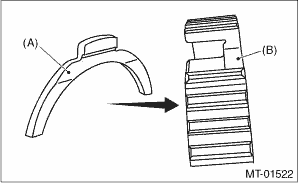
4. Install the baulk ring, needle bearing, 4th drive gear and 4th gear thrust washer to the transmission main shaft.
NOTE:
Align the baulk ring and sleeve & hub assembly with the key groove.
|
(A) |
Groove |
|
(B) |
Face this surface to the 4th gear side. |
5. Press-fit the ball bearing into the rear section of transmission main shaft using ST1, ST2 and a press.
CAUTION:
Do not apply a load in excess of 10 kN (1 ton, 1.1 US ton, 1.0 Imp ton).
| ST1 899714110 | REMOVER |
| ST2 499877000 | RACE 4-5 INSTALLER |
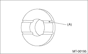
6. Using the ST1 and ST2, install the 5th gear thrust washer and 5th needle bearing race onto the rear section of transmission main shaft.
CAUTION:
Do not apply a load in excess of 10 kN (1 ton, 1.1 US ton, 1.0 Imp ton).
NOTE:
Make sure the thrust washer is oriented in the correct direction.
| ST1 899714110 | REMOVER |
| ST2 499877000 | RACE 4-5 INSTALLER |
|
(A) |
Face this surface to the 5th gear side. |
7. Install rest of the parts to the rear section of the transmission main shaft.
CAUTION:
• Install the baulk lever so that the concave side faces toward the 5th hub.
|
(A) |
Baulk lever |
|
(B) |
5th hub |
• Fit the convex portions of baulk ring with the gaps between baulk levers.
|
(A) |
Baulk ring |
|
(B) |
Baulk lever |
|
(C) |
5th hub |
|
(A) |
Needle bearing |
|
(B) |
5th drive gear |
|
(C) |
Baulk ring |
|
(D) |
5th hub & sleeve No. 2 |
|
(E) |
Lock washer |
|
(F) |
Lock nut |
|
(G) |
Baulk lever |
8. Tighten the lock nuts to the specified torque using ST1 and ST2.
9. Crimp lock nuts in two locations after tightening.
| ST1 499987003 | SOCKET WRENCH (35) |
| ST2 498937000 | TRANSMISSION HOLDER |
Tightening torque:
120 N·m (12.2 kgf-m, 88.5 ft-lb)
10. Attach the needle bearing to the main shaft.
11. Install rest of the parts to the front section of the transmission main shaft.
NOTE:
• When installing the needle bearing, make sure not to damage the raised section on the transmission main shaft
• Face the grooved side towards the input gear.
• Align the groove of the high-low baulk ring to the shifting insert.
|
(A) |
Ball |
|
(B) |
Input low gear spacer |
|
(C) |
Needle bearing |
|
(D) |
Input low gear |
|
(E) |
Friction damper |
|
(F) |
High-low baulk ring |
|
(G) |
Sleeve & hub ASSY |
12. Using ST1 and ST2 install the new snap ring to the transmission main shaft.
NOTE:
Select an appropriate outer snap ring, so that the clearance between the snap ring and hub will become between 0.060 — 0.100 mm (0.0024 — 0.0039 in).
| ST1 499757002 | INSTALLER |
| ST2 499757001 | SNAP RING GUIDE |
|
Snap ring | |
|
Part No. |
Thickness mm (in) |
|
805025051 |
2.42 (0.0953) |
|
805025052 |
2.47 (0.0972) |
|
805025053 |
2.52 (0.0992) |
|
805025054 |
2.57 (0.1012) |
|
805025055 |
2.62 (0.1031) |
|
805025056 |
2.67 (0.1051) |
|
805025057 |
2.72 (0.1071) |
|
805025058 |
2.37 (0.0933) |