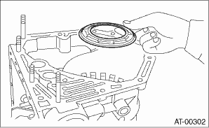
1. Apply ATF to the lips of the low & reverse brake piston, and install the piston.
NOTE:
Take care not to damage the lip seal.
2. Install the return spring.
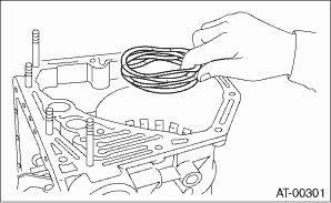
3. Install the spring retainer.
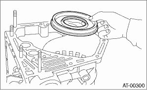
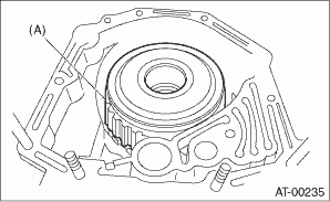
4. Install the one-way clutch inner race.
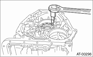
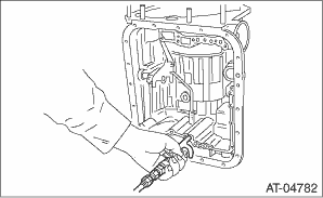
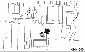
5. Tighten the socket head bolts evenly from the rear side of transmission case.
Tightening torque:
25 N·m (2.5 kgf-m, 18.4 ft-lb)
6. Place the front side of transmission body up.
7. Install the thrust needle bearing.
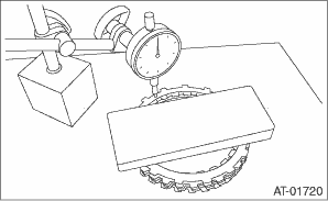
8. Place the dish plate, driven plate, drive plate and retaining plate neatly in this order on surface table.
9. Set the micro gauge to retaining plate, and read its scale.
NOTE:
The value, which is read in the gauge at this time, is zero point.
10. Scale and record the weight “Z” of a flat board which will be put on retaining plate.
NOTE:
• Use a stiff board which does not bend against load as a flat board to be put on retaining plate.
• Use a flat board weighing less than 8.5 kg (18.7 lb).
11. Put the flat board on retaining plate.
12. Using the following formula, read the push/pull gauge, and calculate “N”.
N = 83 N (8.5 kgf, 18.7 lbf) − Z
N: Value indicated on push/pull gauge
83 N (8.5 kgf, 18.7 lbf): Load applied to the clutch plate
Z: Flat board weight
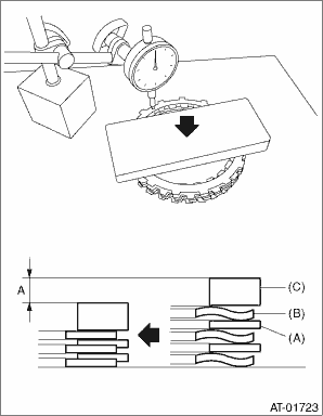
13. Press the center of retaining plate by applying a force of N using push/pull gauge, and then measure and record the height “A”. Measure at three or more locations spaced by equal distances and take the average value.
NOTE:
If measuring in three locations, measure every 120°. If measuring in four locations, measure every 90°.
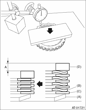
|
(A) |
Dish plate |
|
(B) |
Drive plate |
|
(C) |
Driven plate |
|
(D) |
Retaining plate |
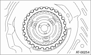
14. Installation of the low & reverse brake:
Install the dish plate, driven plate, drive plate and retaining plate, and then secure them with a snap ring.
NOTE:
Pay attention to the orientation of the dish plate.
|
(A) |
Snap ring |
15. Apply compressed air intermittently to check for operation.
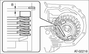
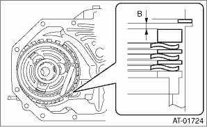
16. Place same thickness shims on both sides to prevent plate from tilting, then measure and record the clearance “B”.
NOTE:
Do not push in the shim down with force to a point where the waves on the drive plate will be crushed.
17. Piston stroke calculation
Calculate from the recorded dimension A and B, and if the service limit is exceeded, replace the drive plate with a new part, and select a retaining plate to make an adjustment so that it is within standard.
T = A + B
T: Piston stroke
A: Amount of drive plate compression
B: Clearance between retaining plate and snap ring
Non-turbo model
Initial standard:
2.15 — 2.65 mm (0.085 — 0.104 in)
Limit thickness:
2.95 mm (0.116 in)
Turbo model
Initial standard:
2.70 — 3.20 mm (0.106 — 0.126 in)
Limit thickness:
3.90 mm (0.154 in)
|
Retaining plate | |
|
Part No. |
Thickness mm (in) |
|
31667AA420 |
3.8 (0.150) |
|
31667AA320 |
4.1 (0.161) |
|
31667AA330 |
4.4 (0.173) |
|
31667AA340 |
4.7 (0.185) |
|
31667AA350 |
5.0 (0.197) |
|
31667AA360 |
5.3 (0.209) |
|
31667AA370 |
5.6 (0.220) |
|
31667AA380 |
5.9 (0.232) |
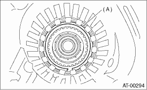
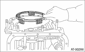
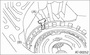
18. Install the leaf spring of the low & reverse brake.
|
(A) |
Leaf spring |
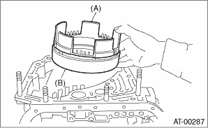
19. Install the 2-4 brake piston and 2-4 brake retainer by aligning the hole of the 2-4 brake retainer with the hole on the transmission case.
|
(A) |
2-4 brake piston |
|
(B) |
2-4 brake piston retainer |
20. Install the 2-4 brake piston spring retainer to the transmission case.
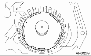
21. Position the snap ring in the transmission. Using ST, press the snap ring into the specified location.
| ST 498677100 | COMPRESSOR |
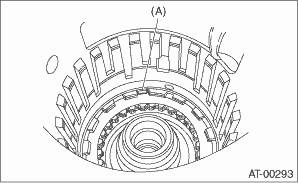
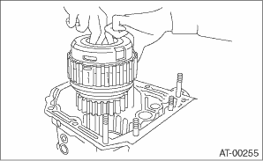
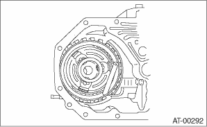
22. Install the planetary gear and low clutch assembly to the transmission case.
NOTE:
Install carefully while rotating the low clutch and planetary gear assembly slowly, being careful not to damage the seal ring.
23. Measure and record a amount of drive plate compression. (non-turbo model)
(1) Place the dish plate, driven plate, drive plate and retaining plate neatly in this order on surface table.
(2) Set the micro gauge to clutch, and read its scale.
NOTE:
The value, which is read in the gauge at this time, is zero point.
(3) Scale and record the weight “Z” of a flat board which will be put on retaining plate.
NOTE:
• Use a stiff board which does not bend against load as a flat board to be put on retaining plate.
• Use a flat board weighing less than 10.2 kg (22.5 lb).
(4) Put the flat board on retaining plate.
(5) Using the following formula, read the push/pull gauge, and calculate “N”.
N = 100 N (10.2 kgf, 22.5 lb) − Z
N: Value indicated on push/pull gauge
100 N (10.2 kgf, 22.5 lb) : Load applied to clutch plate
Z: Flat board weight
(6) Press the center of retaining plate by applying a force of N using push/pull gauge, and then measure and record the height “A”. Measure at three or more locations spaced by equal distances and take the average value.
NOTE:
If measuring in three locations, measure every 120°. If measuring in four locations, measure every 90°.
|
(A) |
Driven plate |
|
(B) |
Drive plate |
|
(C) |
Retaining plate |
24. Install pressure rear plate, drive plate of 2-4 brake, driven plate, retaining plate, and snap ring.
25. Install a new 2-4 brake seal to the transmission case.
26. After all 2-4 brake component parts have been installed, blow in air intermittently and confirm the operation of the brake.
27. Check the piston stroke. (non-turbo model)
(1) Measure clearance “B” between the retaining plate and snap ring.
At this time, do not press down the retaining plate.
(2) Piston stroke calculation
Calculate with A and B dimensions recorded before. If the calculated value exceeds the service limits, replace the drive plate and select and adjust the retaining plate to be within standard values.
T = A + B
T: Piston stroke
A: Amount of drive plate compression
B: Clearance between retaining plate and snap ring
Initial standard:
1.7 — 2.1 mm (0.067 — 0.083 in)
Limit thickness:
2.3 mm (0.091 in)
|
Retaining plate | |
|
Part No. |
Thickness mm (in) |
|
31567AA991 |
5.6 (0.220) |
|
31567AB001 |
5.8 (0.228) |
|
31567AB011 |
6.0 (0.236) |
|
31567AB021 |
6.2 (0.244) |
|
31567AB031 |
6.4 (0.252) |
|
31567AB041 |
6.6 (0.260) |
28. Check the clearance between the retaining plate and snap ring. (turbo model)
NOTE:
If the clearance exceeds the service limits, replace the driven plate and select and adjust the retaining plate to make the clearance fall within initial standard values.
Initial standard:
0.8 — 1.2 mm (0.031 — 0.047 in)
Limit thickness:
1.5 mm (0.059 in)
|
Retaining plate | |
|
Part No. |
Thickness mm (in) |
|
31567AA991 |
5.6 (0.220) |
|
31567AB001 |
5.8 (0.228) |
|
31567AB011 |
6.0 (0.236) |
|
31567AB021 |
6.2 (0.244) |
|
31567AB031 |
6.4 (0.252) |
|
31567AB041 |
6.6 (0.260) |
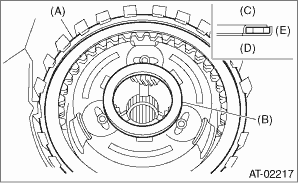
29. Be careful not to mistake the location of the leaf spring to be installed.
|
(A) |
Leaf spring |
|
(B) |
Retaining plate |
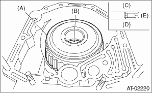
30. Install the thrust needle bearing in the correct direction.
|
(A) |
Snap ring |
|
(B) |
Thrust needle bearing |
|
(C) |
Upside |
|
(D) |
Downside |
|
(E) |
Outside |
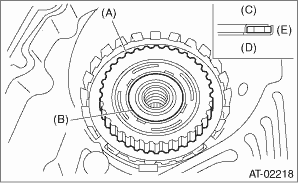
31. Install the front sun gear and the thrust needle bearing.
|
(A) |
Front sun gear |
|
(B) |
Thrust needle bearing |
|
(C) |
Upside |
|
(D) |
Downside |
|
(E) |
Outside |
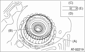
32. Apply vaseline, and attach the thrust needle bearing to the high clutch hub, then engage the splines of the front planetary carrier correctly to install the high clutch hub.
33. Install the thrust needle bearing in the correct direction.
|
(A) |
High clutch hub |
|
(B) |
Thrust needle bearing |
|
(C) |
Upside |
|
(D) |
Downside |
|
(E) |
Outside |
34. Install the high clutch assembly and reverse clutch assembly.
|
(A) |
High clutch ASSY and reverse clutch ASSY |
35. Adjust the total end play. 
36. Install the thrust needle bearing in the correct direction.
|
(A) |
High clutch ASSY and reverse clutch ASSY |
|
(B) |
Thrust needle bearing |
|
(C) |
Upside |
|
(D) |
Downside |
|
(E) |
Outside |
37. Install the oil pump housing assembly along with a new gasket.
38. Install the converter case to the transmission case assembly.
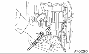
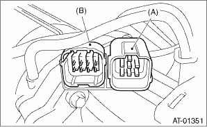
39. Insert the inhibitor switch and transmission harness connector to the stay.
|
(A) |
Transmission harness connectors |
|
(B) |
Inhibitor switch connector |
40. Install the air breather hose.
41. Install the ATF cooler pipe.
42. Install the oil charge pipe with O-ring.
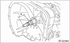
43. Insert the input shaft while rotating it lightly by hand, and then check the amount of protrusion.
Normal protrusion A:
50 — 55 mm (1.97 — 2.17 in)
44. Install the torque converter clutch assembly.
45. Install the transmission assembly to the vehicle.