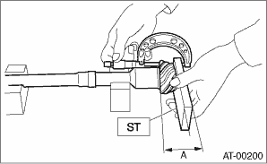
1. Measure the dimension “A” of the drive pinion shaft.
| ST 398643600 | GAUGE |
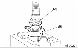
2. Using a press, press-fit the new roller bearing into the specified position.
CAUTION:
Damage may result if too much force is applied to the roller bearing.
|
(A) |
Drive pinion shaft |
|
(B) |
Roller bearing |
3. After applying ATF to a new O-ring and attaching it to the drive pinion shaft, attach the drive pinion collar to the drive pinion shaft.
4. Install the lock washer to drive pinion shaft in the proper direction.
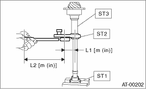
5. Tighten a new lock nut using the ST.
Calculate the lock washer and lock nut specifications using following formula.
T2 = L2/(L1 + L2) × T1
T1: 116 N·m (11.8 kgf-m, 85.6 ft-lb)
[Required torque setting]
T2: Tightening torque
L1: ST2 length 0.072 m (2.83 in)
L2: Torque wrench length
Example:
|
Torque wrench length m (in) |
Tightening torque N·m (kgf-m, ft-lb) |
|
0.4 (15.75) |
98 (10.0, 72.3) |
|
0.45 (17.72) |
100 (10.2, 73.8) |
|
0.5 (19.69) |
101 (10.3, 74.5) |
|
0.55 (21.65) |
102 (10.4, 75.2) |
| ST1 498937110 | HOLDER |
| ST2 499787700 | WRENCH |
| ST3 499787500 | ADAPTER |
NOTE:
Attach ST2 to torque wrench as straight as possible.
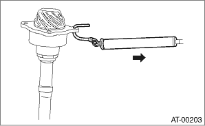
6. Measure the starting torque of the bearing. Make sure the starting torque is within the specified range. If the torque is not within specified range, replace the roller bearing.
Starting torque:
7.6 — 38.1 N (0.775 — 3.88 kgf, 1.7 — 8.6 lbf)
7. Crimp the locknut in 2 locations.
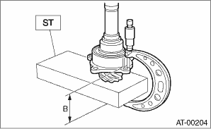
8. Measure the dimension “B” of the drive pinion shaft.
| ST 398643600 | GAUGE |
9. Calculate the thickness “t” (mm) of the drive pinion shim.
t = 6.5±0.0625 − (B − A)
10. Select three or less shims from following table.
|
Drive pinion shim | |
|
Part No. |
Thickness mm (in) |
|
31451AA050 |
0.150 (0.0059) |
|
31451AA060 |
0.175 (0.0069) |
|
31451AA070 |
0.200 (0.0079) |
|
31451AA080 |
0.225 (0.0089) |
|
31451AA090 |
0.250 (0.0098) |
|
31451AA100 |
0.275 (0.0108) |