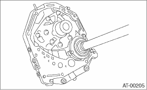
1. Remove the liquid gasket from the mating surface completely.
2. Install the oil pump housing assembly to the converter case, and secure them by tightening the four bolts evenly.
NOTE:
Use an old gasket or aluminum washer to prevent damaging the mating surface of the housing.
Tightening torque:
41 N·m (4.2 kgf-m, 30.2 ft-lb)
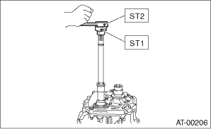
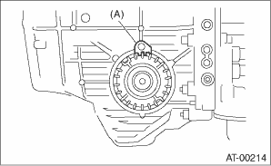
3. Rotate the drive pinion a few times using ST1 and ST2.
| ST1 498937110 | HOLDER |
| ST2 499787700 | WRENCH |
4. Adjust the drive pinion and hypoid driven gear backlash. 
5. Apply lead-free red dye evenly on the surface of three to four teeth of the hypoid driven gear. Rotate the drive pinion back and forward several times. Remove the oil pump housing, and check the teeth contact pattern.
When the contact pattern is not correct, change shim thickness to adjust backlash.
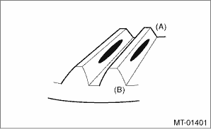
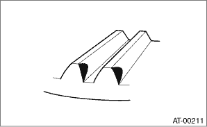
• Correct tooth contact
Check item: Tooth contact surface is slightly shifted toward the toe side under a no-load condition. (When driving, it moves towards the heel side.)
|
(A) |
Toe side |
|
(B) |
Heel side |
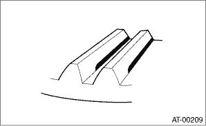
• Face contact
Check item: Backlash is too large.
Contact pattern
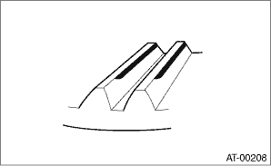
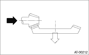
Corrective action: Increase thickness of drive pinion height adjusting washer in order to bring drive pinion close to hypoid driven gear.
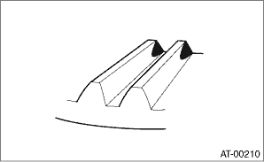
• Flank contact
Check item: Backlash is too small.
Contact pattern
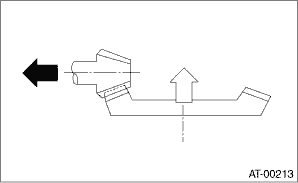
Corrective action: Reduce the thickness of pinion height adjusting washer according to the procedure for bringing the drive pinion away from hypoid driven gear.
• Toe contact (inside contact)
Check item: Teeth contact area is too small.
Contact pattern
Corrective action: Reduce the thickness of the pinion height adjusting washer according to the procedures for moving the drive pinion away from the hypoid driven gear.
• Heel contact (outside end contact)
Check item: Teeth contact area is too small.
Contact pattern
Corrective action: Increase the thickness of the pinion height adjusting washer according to the procedures for moving the drive pinion closer to the hypoid driven gear.
6. If tooth contact is correct, mark the differential side retainer position and loosen. After fitting a new O-ring and oil seal, screw in the differential side retainer to the marked position. Tighten the lock plate with specified torque.
Tightening torque:
25 N·m (2.5 kgf-m, 18.4 ft-lb)
|
(A) |
Lock plate |