• MODEL WITHOUT PUSH BUTTON IGNITION SWITCH
| STEP | CHECK | YES | NO |
|
Is the system name displayed? |
|
Perform the inspection following the diagnostic procedure in the LAN section. |
|
|
While brake pedal is not depressed, is it possible to move the select lever from the “P” range to other ranges? |
Perform the inspection of “SELECT LEVER CANNOT BE LOCKED OR RELEASED”. |
|
|
|
While brake pedal is depressed, is it possible to move the select lever from the “P” range to other ranges? |
|
Perform the inspection of “SELECT LEVER CANNOT BE LOCKED OR RELEASED”. |
|
|
Is it possible to move the select lever from the “N” range to the “P” range? |
|
Perform the inspection of “SELECT LEVER CANNOT BE LOCKED OR RELEASED”. |
|
|
While brake pedal is depressed, is it possible to move the select lever from the “N” range to the “P” range? |
|
Perform the inspection of “SELECT LEVER CANNOT BE LOCKED OR RELEASED”. |
|
|
Can the ignition key be removed? |
Perform the inspection of “KEY INTERLOCK CANNOT BE LOCKED OR RELEASED”. |
|
|
|
Can the ignition key be removed? |
AT shift lock system is normal. |
Perform the inspection of “KEY INTERLOCK CANNOT BE LOCKED OR RELEASED”. |

• MODEL WITH PUSH BUTTON IGNITION SWITCH
| STEP | CHECK | YES | NO |
|
Is the system name displayed? |
|
Perform the inspection following the diagnostic procedure in the LAN section. |
|
|
While brake pedal is not depressed, is it possible to move the select lever from the “P” range to other ranges? |
Perform the inspection of “SELECT LEVER CANNOT BE LOCKED OR RELEASED”. |
|
|
|
While brake pedal is depressed, is it possible to move the select lever from the “P” range to other ranges? |
|
Perform the inspection of “SELECT LEVER CANNOT BE LOCKED OR RELEASED”. |
|
|
Is it possible to move the select lever from the “N” range to the “P” range? |
|
Perform the inspection of “SELECT LEVER CANNOT BE LOCKED OR RELEASED”. |
|
|
While brake pedal is depressed, is it possible to move the select lever from the “N” range to the “P” range? |
AT shift lock system is normal. |
Perform the inspection of “SELECT LEVER CANNOT BE LOCKED OR RELEASED”. |
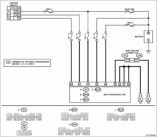
2. BODY INTEGRATED UNIT POWER SUPPLY AND GROUND CIRCUIT

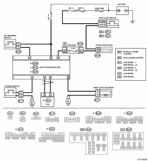
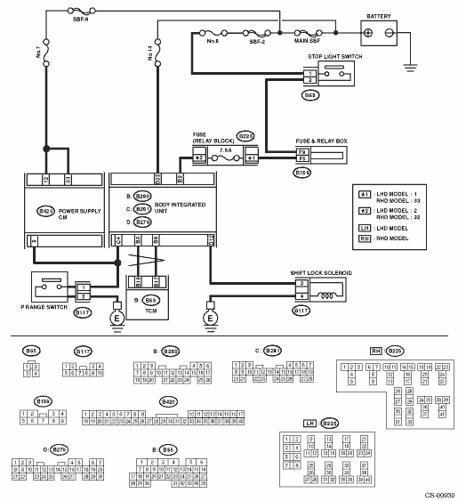
3. SELECT LEVER CANNOT BE LOCKED OR RELEASED
• MODEL WITHOUT PUSH BUTTON IGNITION SWITCH
• MODEL WITH PUSH BUTTON IGNITION SWITCH
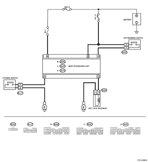
4. KEY INTERLOCK CANNOT BE LOCKED OR RELEASED
NOTE:
Check of this item only applies to models without a push button ignition switch.