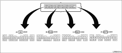
1. MODEL WITHOUT PUSH BUTTON IGNITION SWITCH

|
Item |
Connector No. |
Terminal No. |
Input/Output signal |
|
Measured value and measuring conditions | |||
|
Battery power supply |
B279 |
22 |
9 — 16 V |
|
B280 |
6 | ||
|
Ignition power supply |
B280 |
1 |
10 — 15 V when ignition switch is at ON or START. |
|
7 |
10 — 15 V when ignition switch is at ACC. | ||
|
TCM (“P” range) |
B280 |
3 |
Pulse signal |
|
9 | |||
|
Stop light switch |
B280 |
2 |
9 — 16 V when stop light switch is ON. 0 V when stop light switch is OFF. |
|
“P” range switch |
B281 |
4 |
0 V when select lever is in “P” range. 9 — 16 V when select lever is in other positions than “P” range. |
|
Shift lock solenoid output |
B279 |
12 |
8.5 — 16 V when shift lock is released. 0 V when shift lock is operating. |
|
Key warning switch signal |
B279 |
2 |
9 — 16 V when key is inserted. 0 V when key is removed. |
|
Key lock solenoid output |
B279 |
11 |
7.5 — 16 V when select lever is in other positions than “P” range and ignition switch is at ON. 0 V at other conditions than above. |
|
Ground |
i84 |
28 |
— |
|
B280 |
17 | ||
|
B281 |
20 | ||
|
B279 |
27 |
2. MODEL WITH PUSH BUTTON IGNITION SWITCH
|
Item |
Connector No. |
Terminal No. |
Input/Output signal |
|
Measured value and measuring conditions | |||
|
Battery power supply |
B279 |
22 |
9 — 16 V |
|
B280 |
6 | ||
|
Ignition power supply |
B280 |
1 |
10 — 15 V when ignition switch is at ON or START. |
|
7 |
10 — 15 V when ignition switch is at ACC. | ||
|
TCM (“P” range) |
B280 |
3 |
Pulse signal |
|
9 | |||
|
Stop light switch |
B280 |
2 |
9 — 16 V when stop light switch is ON. 0 V when stop light switch is OFF. |
|
“P” range switch |
B281 |
4 |
0 V when select lever is in “P” range. 9 — 16 V when select lever is in other positions than “P” range. |
|
Shift lock solenoid output |
B279 |
12 |
8.5 — 16 V when shift lock is released. 0 V when shift lock is operating. |
|
Ground |
i84 |
28 |
— |
|
B280 |
17 | ||
|
B281 |
20 | ||
|
B279 |
27 |