NOTE:
• Apply grease to individual parts before assembly. 
Grease:
Shaft assembly sliding portion, lever set sliding portion
Multemp #6129 or equivalent
Shaft assembly spline portion
Multemp 0A-171
Pinion gear, internal gear assembly matching area to pinion gear
Molykote® AG-650 or equivalent
• Refer to “Exploded view” of “General Description” for the tightening torque of bolts, screws and nuts.
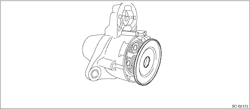
1. Attach the overrunning clutch to the shaft assembly.
2. Attach the stopper to the shaft assembly according to the following procedures.
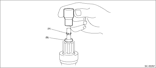
(1) Use an appropriate tool (such as a socket wrench of the correct size) to lightly tap on the ring and fit it to the shaft groove.
NOTE:
Use a new stopper set (ring and stopper).
|
(A) |
Ring |
(B) |
Stopper |
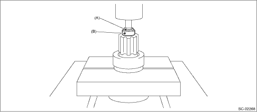
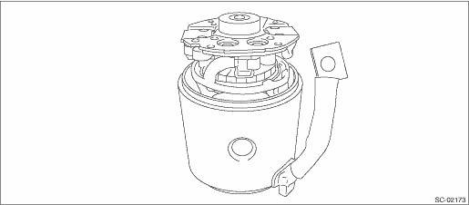
(2) Use a press to press-fit the stopper onto the ring.
|
(A) |
Ring |
(B) |
Stopper |
3. Attach the shaft assembly to the front bracket while being careful of the following points.
(1) Lever direction
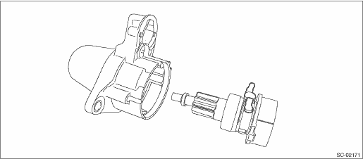
(2) Internal gear assembly position
4. Attach the plate.
|
(A) |
Plate |
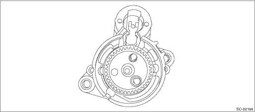
5. Install the gear assembly.
6. Attach gaskets A and B while being careful of the installation position.
NOTE:
Face the two indents in gasket A upward when installing.
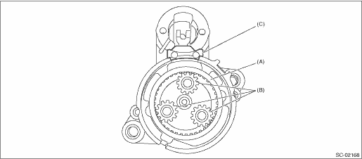
|
(A) |
Gasket A |
(B) |
Gear ASSY |
(C) |
Gasket B |
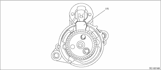
7. Install the plate being careful of the attachment direction.
8. Insert the armature into the yoke.
9. Attach the brush holder to the yoke according to the following procedures.
(1) Push the brush into the brush holder and, using appropriate tools, (proper size socket wrenches, etc.), hold in place and insert the armature into the proper position.
(2) Match the brush holder to the yoke mark and attach the rear cover. Temporarily attach with screws.
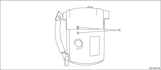
|
(A) |
Mark |
10. Attach the ball, and attach the yoke to match the front bracket groove.
11. Attach the through bolts and tighten the attachment screws.
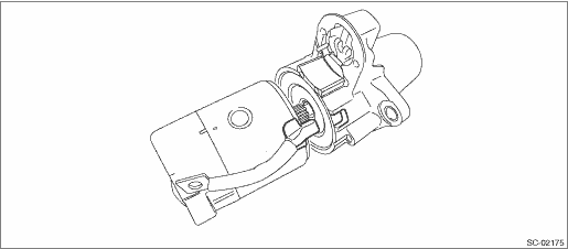
12. Attach the magnet switch assembly to the front bracket according to the following procedures.
(1) Insert the plunger and plunger spring into the magnet switch.
(2) Hook the protrusion on the plunger onto the lever end, then install to the front bracket.
|
(A) |
Magnet switch ASSY |
13. Attach the connector to terminal M of the magnet switch assembly.