CAUTION:
• Protect the fuel delivery pipes from contacting tools or other parts by wrapping with nylon cloth or paper towels.
• Be careful not to allow foreign matter to get into the fuel system.
• Always inspect all joints for fuel leaks after replacing pipes.
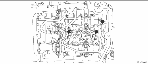
1. Install the fuel pipe holder on one side.
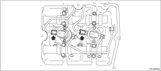
2. Pass the fuel delivery pipes through the cap holes.
NOTE:
Be careful to install the caps to the fuel delivery pipes in the correct installation position.
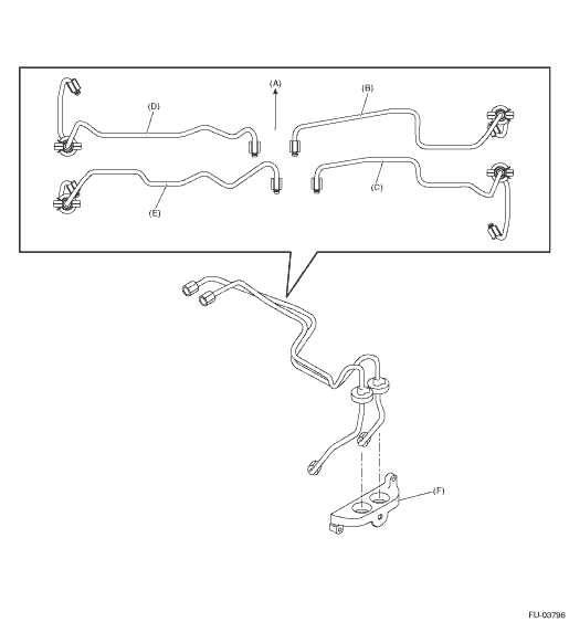
|
(A) |
Front |
(C) |
#3 |
(E) |
#4 |
|
(B) |
#1 |
(D) |
#2 |
(F) |
Cap |
3. Install the fuel delivery pipes to their original position.
4. Hang the fuel delivery pipes on the outer side engine until the liquid gasket can be applied to the cap.
5. Apply liquid gasket to the caps.
NOTE:
Install within 5 min. after applying liquid gasket.
Liquid gasket:
THREE BOND 1217G (Part No. K0877Y0100) or equivalent
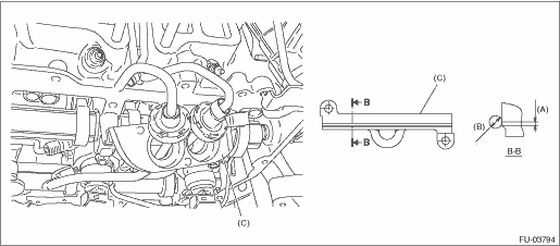
|
(A) |
1 mm (0.0394 in) or less |
(B) |
2.5 — 4.5 mm (0.0984 — 0.1772 in) |
(C) |
Cap |
6. Install cap.
Tightening torque:
6.4 N·m (0.7 kgf-m, 4.7 ft-lb)
7. Install the fuel injectors to the cylinder head and temporarily tighten the bolts. 
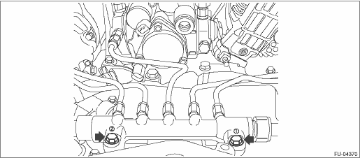
8. Temporarily tighten the fuel delivery pipe nuts of the common rail assembly.
9. Temporarily tighten the fuel delivery pipe nuts of the fuel injectors.
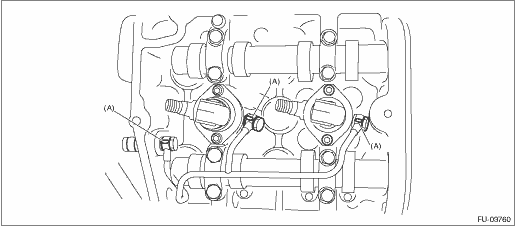
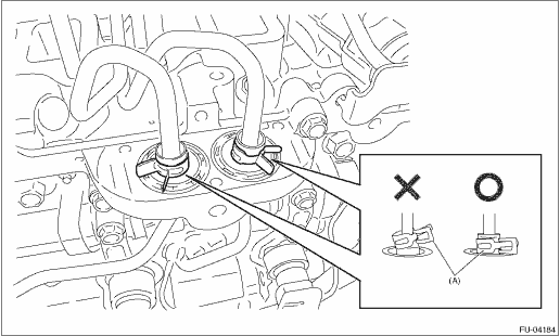
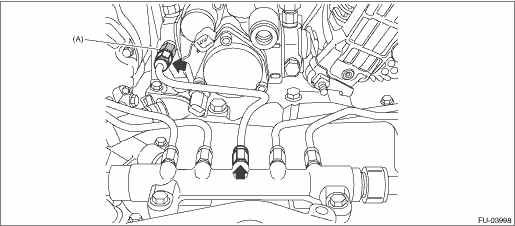
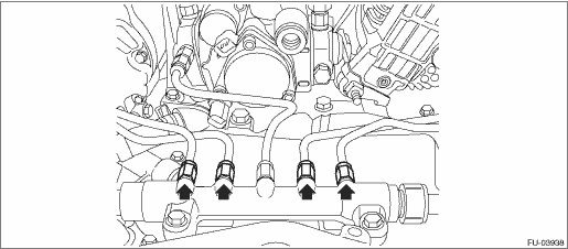
10. Install the fuel return pipes, and tighten the union screws by hand as much as possible.
NOTE:
Use new gaskets (A).
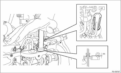
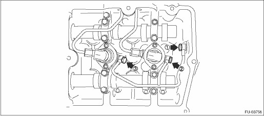
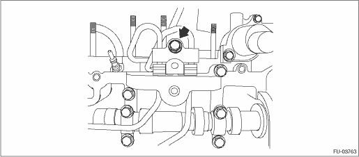
11. Remove the seal protection case, and use the ST to, slowly and by hand, press-fit the seal to the to the cap.
NOTE:
• Apply a coat of engine oil to the periphery of the seal.
• The seal protrusion (A) should be 0.5 mm (0.0197 in) or less.
CAUTION:
Make sure that the tool does not contact the fuel delivery pipes.
| ST 18674AA010 | INSTALLER |
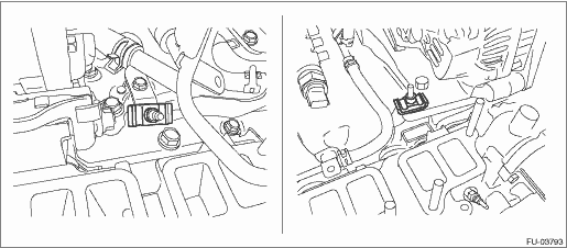
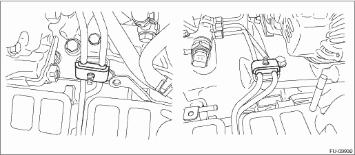
12. Install the clips to the outer side of the engine positioned as shown in the following figure.
|
(A) |
Clip |
13. Temporarily tighten the fuel pipe holder and fuel pipe holder stay.
14. Tighten the fuel pipe holder stay bolts.
Tightening torque:
6.4 N·m (0.7 kgf-m, 4.7 ft-lb)
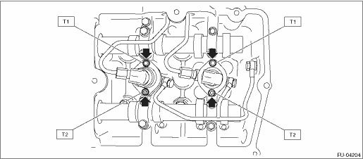
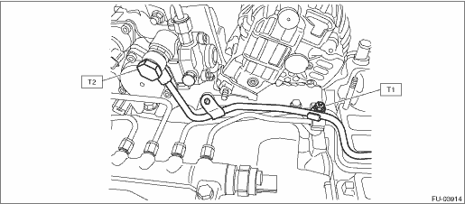
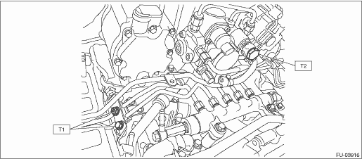
15. Tighten the fuel injector bolts.
CAUTION:
• Always start tightening from the upper bolts first.
• Be careful not to overtighten the lower bolts.
Tightening torque:
T1: 7.7 N·m (0.8 kgf-m, 5.7 ft-lb)
T2: Tighten to 3.5 N·m (0.4 kgf-m, 2.6 ft-lb) of torque, and then tighten a further 85° — 95°
16. Tighten the fuel return pipe union screws.
NOTE:
Tighten in order starting from where joined with the cylinder head and moving towards the front of the engine.
Tightening torque:
12.5 N·m (1.3 kgf-m, 9.2 ft-lb)
17. Make sure there are no air leaks from fuel return pipe joints.
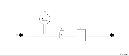
(1) Connect an air pressure gauge to the fuel return pipe on top of the engine to create the circuit shown in the figure below, and apply 250 kPa (2.5 kg-cm2) of air pressure.
CAUTION:
Always use the specified air pressure. If air pressure is too high, air will enter the high-pressure pipe.
Circuit Figure
|
(A) |
Engine (To fuel return pipe) |
(B) |
Air pressure gauge |
(C) |
Gate valve |
|
(D) |
Pressure regulator |
|
(A) |
LH side |
(B) |
RH side |
(2) Close the gate valve, maintain air pressure for 60 seconds, and verify that there is no leakage from fuel return pipe joints.
NOTE:
• Apply engine oil to fuel return pipe joints and check for bubbles indicating air leakage.
• Check that the air pressure gauge indicator does not move downward.
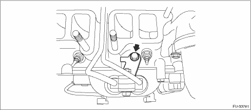
18. Tighten the common rail assembly bolts.
NOTE:
Start tightening from the bolt on the common rail pressure sensor side.
Tightening torque:
19 N·m (1.9 kgf-m, 14.0 ft-lb)
19. Tighten the fuel delivery pipe nuts between the fuel pump and common rail assembly.
CAUTION:
Be careful not to apply an unbalanced load when tightening.
NOTE:
Perform the work while fixing the holder (A) in figure below with a spanner.
Tightening torque:
35 N·m (3.6 kgf-m, 25.8 ft-lb)
20. Tighten the fuel pipe holder bolts.
Tightening torque:
6.4 N·m (0.7 kgf-m, 4.7 ft-lb)
21. Tighten the fuel delivery pipes of the fuel injectors.
Tightening torque:
35 N·m (3.6 kgf-m, 25.8 ft-lb)
22. Tighten the fuel delivery pipe nuts of the common rail assembly.
Tightening torque:
35 N·m (3.6 kgf-m, 25.8 ft-lb)
23. Install the fuel pipe holder on one side.
24. Install the fuel pipe.
NOTE:
Use a new gasket.
Tightening torque:
T1: 6.4 N·m (0.7 kgf-m, 4.7 ft-lb)
T2: 17 N·m (1.7 kgf-m, 12.5 ft-lb)
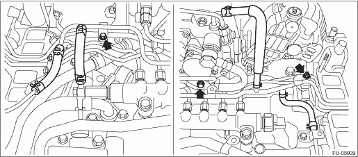
• LHD model
• RHD model
25. Install the fuel return pipes.
Tightening torque:
6.4 N·m (0.7 kgf-m, 4.7 ft-lb)
• LHD model
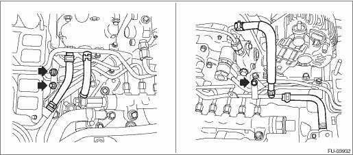
• RHD model
26. For the remaining parts, install in the reverse order of removal.
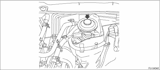
27. Pump the priming pump on top of the fuel filter assembly to fill the fuel system with fuel.
NOTE:
Pump the priming pump until it is stiff.
28. Check for fuel leakage.
Install in the reverse order of removal.
NOTE:
• Use a new gasket.
• Tighten the fuel return pipe union screws inside the locker cover by hand as much as possible, and then tighten to the specified torque.
• Tighten the fuel return pipe inside the locker cover in order starting from the joint section with the cylinder head towards the front side of the engine.
• Install each hose with the pink alignment mark facing up.
• Refer to “COMPONENT” for the tightening torque of bolts and nuts.
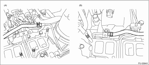
• Install clips in the positions shown in the following figure.
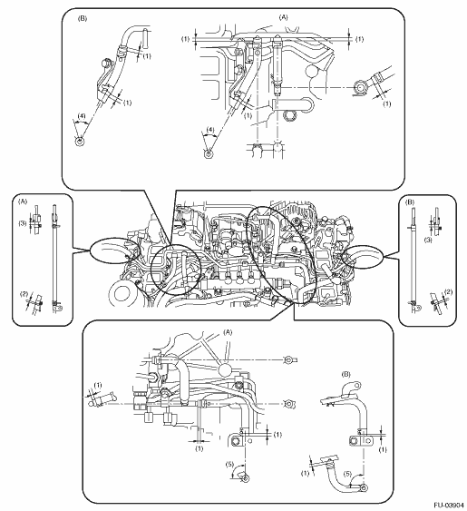
|
(A) |
LHD model |
(B) |
RHD model |
||
|
(1) |
3 — 5 mm (0.1181 — 0.1969 in) |
(3) |
5 — 10 mm (0.1969 — 0.3937 in) |
(5) |
Approx. 90° |
|
(2) |
5 mm (0.1969 in) |
(4) |
Approx. 45° |