CAUTION:
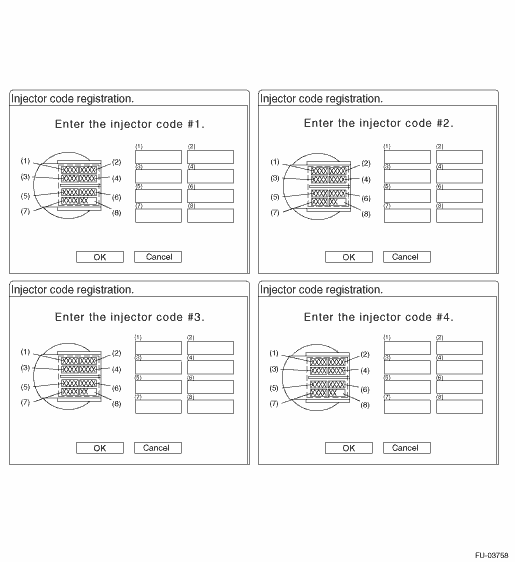
• Before installing the fuel injectors, always write down the ID marked on the top of the fuel injectors.
• When installing the fuel injectors, check the tips of the fuel injectors for damage and that there is no foreign matter attached.
• When installing the fuel injectors, always replace the fuel delivery pipes with new parts.
1. Write down the ID on the top of the fuel injectors for every cylinder.
NOTE:
Use copies of or print out this page.

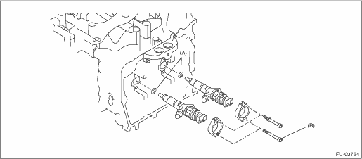
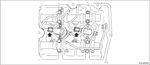
2. Install the fuel injectors to the holder and temporarily install to the cylinder head.
NOTE:
• Use new gaskets (A).
• Use a new bolts (B).
• Be careful to install upper and lower bolts in the correct location.
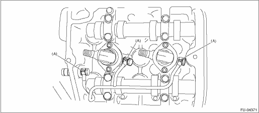
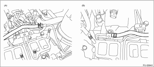
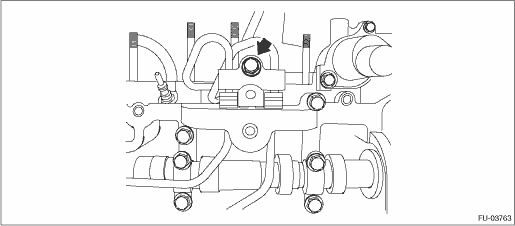
3. Install the fuel return pipes, and tighten the union screws by hand as much as possible.
NOTE:
Use new gaskets (A).
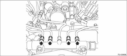
4. Install the fuel delivery pipes, and temporarily tighten all nuts except for cap nuts and all bolts. 
5. Tighten the fuel pipe stay bolts.
Tightening torque:
6.4 N·m (0.7 kgf-m, 4.7 ft-lb)
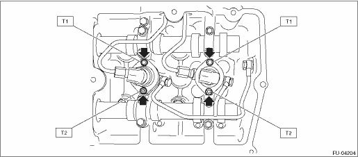
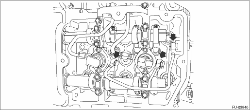
6. Tighten the fuel injector bolts.
CAUTION:
• Always start tightening from the upper bolts first.
• Be careful not to overtighten the lower bolts.
Tightening torque:
T1: 7.7 N·m (0.8 kgf-m, 5.7 ft-lb)
T2: Tighten to 3.5 N·m (0.4 kgf-m, 2.6 ft-lb) of torque, and then tighten a further 85° — 95°
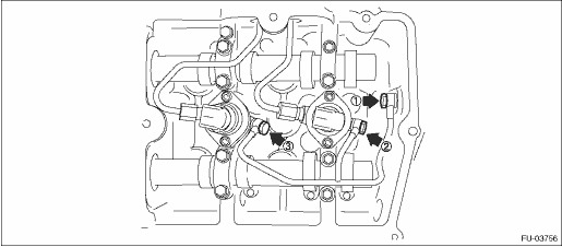
7. Tighten the fuel return pipe union screws.
NOTE:
Tighten in order starting from where joined with the cylinder head and moving towards the front of the engine.
Tightening torque:
12.5 N·m (1.3 kgf-m, 9.2 ft-lb)
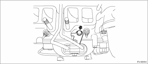
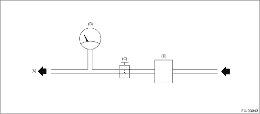
8. Make sure there are no air leaks from fuel return pipe joints.
(1) Connect an air pressure gauge to the fuel return pipe on top of the engine to create the circuit shown in the figure below, and apply 250 kPa (2.5 kg-cm2) of air pressure.
CAUTION:
Always use the specified air pressure. If air pressure is too high, air will enter the high-pressure pipe.
NOTE:
Check each side individually.
Circuit Figure
|
(A) |
Engine (To fuel return pipe) |
(B) |
Air pressure gauge |
(C) |
Gate valve |
|
(D) |
Pressure regulator |
|
(A) |
LH side |
(B) |
RH side |
(2) Close the gate valve, maintain air pressure for 60 seconds, and verify that there is no leakage from fuel return pipe joints.
NOTE:
• Apply engine oil to fuel return pipe joints and check for bubbles indicating air leakage.
• Check that the air pressure gauge indicator does not move downward.
9. Tighten the fuel pipe holder bolts.
Tightening torque:
6.4 N·m (0.7 kgf-m, 4.7 ft-lb)
10. Tighten the fuel delivery pipes of the fuel injectors.
Tightening torque:
35 N·m (3.6 kgf-m, 25.8 ft-lb)
11. Tighten the fuel delivery pipes of the common rail assembly.
Tightening torque:
35 N·m (3.6 kgf-m, 25.8 ft-lb)
12. For the remaining parts, install in the reverse order of removal.
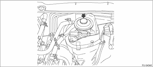
13. Pump the priming pump on top of the fuel filter assembly to fill the fuel system with fuel.
NOTE:
Pump the priming pump until it is stiff.
14. Using the Subaru Select Monitor, confirm that the IDs of the fuel injectors for each cylinder that were written down match the IDs registered in the ECM.
NOTE:
If any ID registered in the ECM does not match, perform ID registration.
15. If any fuel injector is replaced, perform compulsory learning mode.
16. Check for fuel leakage.