NOTE:
The illustration shows RHD model. Perform the same procedures for LHD model.
1. Degrease the connections of air duct hose (LH) and air duct hose (RH).
2. Install the intercooler stays and air duct hose (LH).
Tightening torque:
Air intake duct
5.5 N·m (0.6 kgf-m, 4.1 ft-lb)
Intercooler stay
19 N·m (1.9 kgf-m, 14.0 ft-lb)
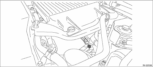
3. Install the air duct hose (RH) to the intercooler.
NOTE:
Install the clamp 5 — 7 mm (0.1969 — 0.2756 in) away from the end of the hose. Do not let the clamp ride over the bulge.
Tightening torque:
5.5 N·m (0.6 kgf-m, 4.1 ft-lb)
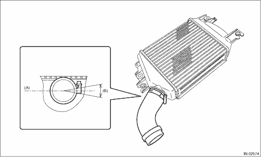
|
(A) |
Intercooler tank level surface |
(B) |
20° |
|
(A) |
5 — 7 mm (0.1969 — 0.2756 in) |
(C) |
Intercooler |
(E) |
Air duct hose (RH) |
|
(B) |
Clamp |
(D) |
Bulge |
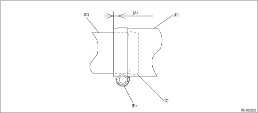
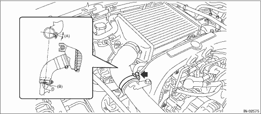
4. Tighten the air duct hose clamp.
NOTE:
Install the clamp at the following position from the end of the hose. Do not let the clamp ride over the bulge.
• Intercooler side: 5 — 7 mm (0.1969 — 0.2756 in)
• Air intake duct side: 3 — 5 mm (0.1181 — 0.1969 in)
Tightening torque:
5.5 N·m (0.6 kgf-m, 4.1 ft-lb)
|
(A) |
0° — 20° |
(B) |
Assemble by aligning the hose marking and clamp mark to the stay concave section. | ||
|
(A) |
Intercooler side: 5 — 7 mm (0.1969 — 0.2756 in) Air intake duct side: 3 — 5 mm (0.1181 — 0.1969 in) |
(C) |
Intercooler or intake air duct |
(E) |
Air duct hose |
|
(B) |
Clamp |
(D) |
Bulge |
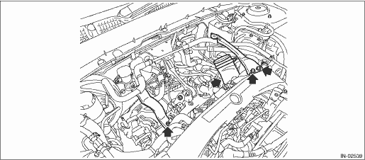
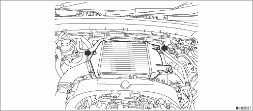
5. Install the intercooler.
Tightening torque:
19 N·m (1.9 kgf-m, 14.0 ft-lb)
6. Install the collector cover.