1. Be sure to perform cylinder head gasket selection when the following work has been performed.
• Cylinder block replacement
• Crankshaft replacement
• Connecting rod replacement
• Piston replacement
• Crankshaft bearing replacement
• Connecting rod bearing replacement
NOTE:
For the selection procedures of the cylinder head gasket, refer to the cylinder block attachment procedure 13). 
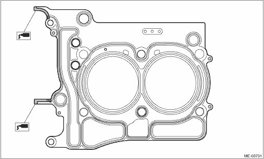
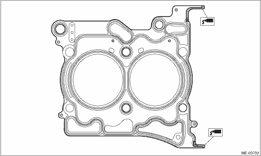
2. Apply liquid gasket to both sides of the cylinder head gasket as shown in the figure.
CAUTION:
• Do not apply liquid gasket excessively. If too much is applied, remove any liquid gasket that is squeezed out.
• Even if cylinder head gasket selection of procedure 1) is not required, always use new gaskets of the same rank as that used before removal.
NOTE:
Install within 5 min. after applying liquid gasket.
Liquid gasket:
THREE BOND 1217G (Part No. 0877Y0100) or equivalent
Liquid gasket applying diameter:
3.5±1.0 mm (0.1378±0.0394 in)
• LH side
• RH side
3. Attach the cylinder head gasket.
NOTE:
Check that liquid gasket is squeezed out from the cylinder head gasket.
4. Attach the cylinder head to the cylinder block.
CAUTION:
Be careful not to scratch the mating surface of cylinder head and cylinder block.
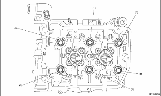
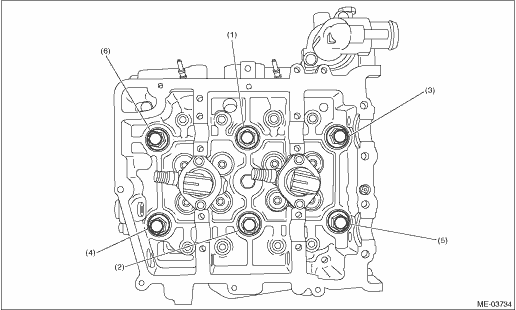
5. Tighten the cylinder head bolts.
(1) Apply a thin coat of engine oil to washers and cylinder head bolt threads.
(2) Tighten the cylinder head bolts with a torque of 60 N·m (6.1 kgf-m, 44.3 ft-lb) in the numerical sequence as shown in the figure.
(3) Loosen all bolts in the reverse order of step (2).
(4) Tighten the cylinder head bolts with a torque of 20 N·m (2.0 kgf-m, 14.8 ft-lb) in the numerical sequence as shown in the figure.
(5) Retighten the cylinder head bolts with a torque of 60 N·m (6.1 kgf-m, 44.3 ft-lb) in the numerical sequence as shown in the figure.
(6) Tighten the bolts in numerical order as shown in the figure by 90°.
(7) Retighten the bolts in numerical order as shown in the figure by 90°.
CAUTION:
The tightening angle of the bolt should not exceed 90°.
• LH side
• RH side
6. Attach the flange bolts indicated in the figure to the cylinder head.
Tightening torque:
LH side
18 N·m (1.8 kgf-m, 13.3 ft-lb)
RH side
6.4 N·m (0.7 kgf-m, 4.7 ft-lb)
• LH side
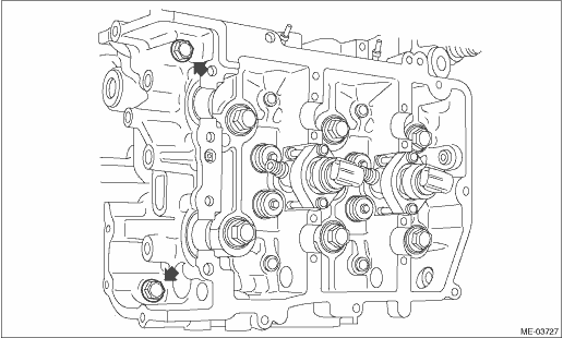
• RH side
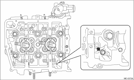
7. Attach the return pipe and water pipe fixture bolts to the rear and bottom of cylinder head (LH).
8. Attach the water pipe fixture bolt to the rear of cylinder head (RH).
9. Attach the EGR cooler to the rear of cylinder head (RH).
10. Attach the fuel injector and glow plug to the cylinder head.
NOTE:
Step 10) is only performed when the fuel injector and glow plug are removed from the cylinder head.
11. Install the camshaft.
12. Perform a valve clearance inspection.
13. Attach the fuel delivery pipe and return pipe.
14. Install the rocker cover.
15. Install the intake manifold.
16. Install the cam sprocket.
NOTE:
Step 16 is only performed when the cam sprocket is removed.
17. Install the timing chain assembly.
18. Install the chain cover.
19. Attach the oil level gauge and oil level gauge guide to the chain cover.
20. Install the camshaft position sensor.
21. Install the vacuum pump.
22. Install the scavenger pump.
23. Install the crank pulley.
24. Install the V-belt tensioner.
25. Install the V-belts.
26. Install the engine to the vehicle.