1. Visually inspect to make sure that there are no cracks, scratches or other damage.
2. Use liquid penetrant tester on the important sections to check for fissures.
3. Check that there are no traces of gas leaking or water leaking on the gasket attachment surface.
4. Check the oil passages for clogging.
5. Check for warpage of mating surfaces of the cylinder head and cylinder block using a straight edge and thickness gauge. If the warpage exceeds the limit, replace the cylinder block.
Warping limit:
0.020 mm (0.0008 in)
Standard height of cylinder block:
220 mm (8.6614 in)
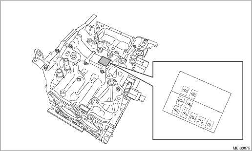
1. The cylinder bore size is stamped on the front upper face of the cylinder block.
NOTE:
• Measurement should be performed at a temperature of 20°C (68°F).
• Standard sized pistons are classified into two grades, “A” and “B”. These grades should be used as guide lines in selecting a standard piston.
Standard diameter:
A: 86.005 — 86.015 mm (3.3860 — 3.3864 in)
B: 85.995 — 86.005 mm (3.3856 — 3.3860 in)
|
(A) |
#1 cylinder bore size mark |
(D) |
#4 cylinder bore size mark |
(G) |
#3 main journal size marks |
|
(B) |
#2 cylinder bore size mark |
(E) |
#5 main journal size marks |
(H) |
#2 main journal size marks |
|
(C) |
#3 cylinder bore size mark |
(F) |
#4 main journal size marks |
(I) |
#1 main journal size marks |
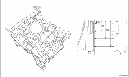
2. Measurement method for cylinder inner diameters:
Using a cylinder bore gauge, measure the inner diameter of each cylinder in both the thrust and piston pin directions at the heights shown in the figure.
NOTE:
Measurement should be performed at a temperature of 20°C (68°F).
Cylindricality:
Standard
0.030 mm (0.0012 in)
Out-of-roundness:
Standard
0.010 mm (0.0004 in)
|
(A) |
Thrust direction |
(B) |
Piston pin direction |
||
|
H1: |
10 mm (0.3937 in) |
H2: |
45 mm (1.7717 in) |
H3: |
80 mm (3.1496 in) |
|
H4: |
115 mm (4.5276 in) |
3. When the piston is to be replaced due to general or cylinder wear, select a suitable sized piston by measuring the piston clearance.
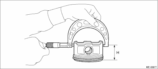
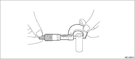
4. Measure outer diameter of each piston.
Measure the outer diameter of each piston at the height as shown in the figure. (Thrust direction)
NOTE:
Measurement should be performed at a temperature of 20°C (68°F).
Piston grade point H:
53.3 mm (2.0984 in)
Piston outer diameter:
Standard
A: 85.94 — 85.95 mm (3.3835 — 3.3839 in)
B: 85.93 — 85.94 mm (3.3831 — 3.3835 in)
0.25 mm (0.0098 in) oversize
86.18 — 86.20 mm (3.3929 — 3.3937 in)
0.50 mm (0.0197 in) oversize
86.43 — 86.45 mm (3.4027 — 3.4035 in)
5. Calculate the clearance between cylinder and piston.
NOTE:
Measurement should be performed at a temperature of 20°C (68°F).
Cylinder to piston clearance at 20°C (68°F):
Standard
0.055 — 0.075 mm (0.0022 — 0.0030 in)
6. Boring and honing
(1) If the values of taper, out-of-roundness, or cylinder-to-piston clearance measured is out of standard, or if there is any damage on the cylinder wall, rebore it so that an oversize piston can be used.
CAUTION:
When any of the cylinders needs reboring, all other cylinders must be bored at the same time, and use oversize pistons.
(2) If the cylinder inner diameter exceeds the limit after boring and honing, replace the cylinder block.
NOTE:
Immediately after reboring, the cylinder diameter may differ from its real diameter due to its high temperature. Thus, pay attention to this when measuring the cylinder diameter.
Cylinder inner diameter boring limit
To 86.505 mm (3.4057 in)
1. Check the piston and piston pin for damage, cracks or wear.
2. Check the piston ring groove for wear or damage. Replace if faulty.
3. Make sure that the piston pin can be inserted into the piston pin hole with a thumb at 20°C (68°F). Replace if faulty.
Standard clearance between piston pin and hole in piston:
Standard
0.012 — 0.026 mm (0.0005 — 0.0010 in)
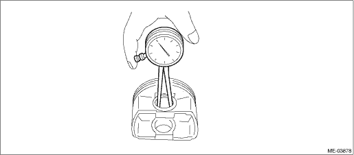
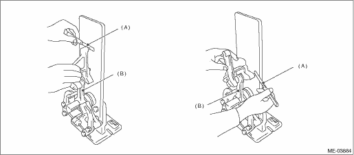
4. Check the snap ring installation groove (A) on the piston for burr. If necessary, remove burr from the groove so that the piston pin can lightly move.
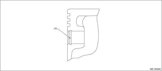
5. Check the piston pin snap ring for distortion, cracks and wear.
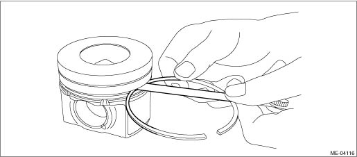
1. If the piston ring is broken, damaged and worn, or if its tension is insufficient, or when the piston is replaced, replace the piston ring with a new part of the same size as the piston.
NOTE:
• The top ring and second ring have the mark to determine the direction for installing. When attaching the ring to the piston, face these marks towards the top side.
• The oil ring consists of the rail and expander. When attaching the oil ring to the piston, pay attention to the position of the ring gap.
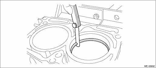
2. Using the piston, insert the piston ring and oil ring into the cylinder so that they are perpendicular to the cylinder wall, and measure the piston ring gap with a thickness gauge.
|
Standard mm (in) | ||
|
Piston ring gap |
Top ring |
0.20 — 0.30 (0.0079 — 0.0118) |
|
Second ring |
0.45 — 0.60 (0.0177 — 0.0236) | |
|
Oil ring |
0.20 — 0.45 (0.0079 — 0.0177) | |
3. Measure the clearance between piston ring and piston ring groove with a thickness gauge.
NOTE:
Before measuring the clearance, clean the piston ring and piston ring groove.
(1) Measure the top ring groove gap.
Push to compress the top ring to align the piston side face and top ring periphery outer face, and lift the top ring to piston ring groove upper side and measure the clearance of piston ring groove lower side.
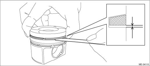
(2) Measure the second ring groove gap.
|
Standard mm (in) | ||
|
Clearance between piston ring and piston ring groove |
Top ring |
0.07 — 0.13 (0.0028 — 0.0051) |
|
Second ring |
0.04 — 0.08 (0.0016 — 0.0031) | |
1. Replace the connecting rod, if the large or small end thrust surface is damaged.
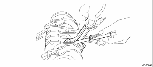
2. Check for bend or twist using a connecting rod aligner. Replace the connecting rod if it has the bend or twist.
Limit of bend or twist per 100 mm (3.9370 in) in length:
0.10 mm (0.0039 in)
|
(A) |
Thickness gauge |
(B) |
Connecting rod |
3. Install the connecting rod with bearings attached to the crankshaft, and measure the thrust clearance using a thickness gauge. If the thrust clearance exceeds the standard or uneven wear is found, replace the connecting rod.
Connecting rod thrust clearance:
Standard
0.070 — 0.330 mm (0.0028 — 0.0130 in)
4. Inspect the connecting rod bearing for scar, peeling, seizure, melting, wear, etc.
5. Measure the oil clearance on each connecting rod bearing using plastigauge. If any oil clearance is not within the standard, replace the defective bearing with a new part of standard size or undersize as necessary. (See the table below.)
Connecting rod oil clearance:
Standard:
0.017 — 0.050 mm (0.0007 — 0.0020 in)
|
Unit: mm (in) | ||
|
Bearing |
Bearing size (Thickness at center) |
Outer diameter of crank pin |
|
Standard |
1.992 — 2.008 (0.0784 — 0.0791) |
54.976 — 55.000 (2.1644 — 2.1654) |
|
0.03 (0.0012) Undersize |
2.010 — 2.018 (0.0791 — 0.0794) |
54.946 — 54.970 (2.1632 — 2.1642) |
|
0.05 (0.0020) Undersize |
2.020 — 2.028 (0.0795 — 0.0798) |
54.926 — 54.950 (2.1624 — 2.1634) |
|
0.25 (0.0098) Undersize |
2.120 — 2.128 (0.0835 — 0.0838) |
54.726 — 54.750 (2.1546 — 2.1555) |
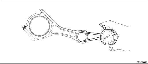
6. Inspect the bushing at connecting rod small end, and replace if worn or damaged. Also measure the piston pin clearance at the small end of the connecting rod.
Clearance between piston pin and bushing:
Standard:
0.012 — 0.036 mm (0.0005 — 0.0014 in)
6. CRANKSHAFT AND CRANKSHAFT BEARING
1. Clean the crankshaft completely, and check it for cracks using liquid penetrant tester. Replace if defective.
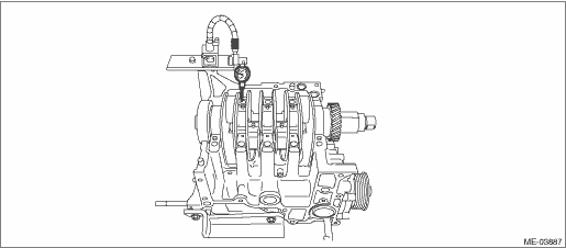
2. Check the crankshaft for bend, and repair or replace if needed. If it exceeds the limit, correct or replace it.
NOTE:
If a suitable V-block is not available, install #1 and #5 crankshaft bearings on the cylinder block, and position the crankshaft on these bearings, and check for bending of the crankshaft using a dial gauge.
Crankshaft bend limit:
0.035 mm (0.0014 in)
3. Inspect the crank journal and crank pin for wear. If they are not within the standard, replace the bearing with a suitable (undersize) one, and replace or grind to correct the crankshaft as necessary. When grinding the crank journal or crank pin, finish them to the specified dimensions according to the undersize bearing to be used.
Crank pin:
Out-of-roundness
0.005 mm (0.0002 in)
Cylindricality
0.006 mm (0.0002 in)
Grinding limit (dia.)
To 54.750 mm (2.1555 in)
Crank journal:
Out-of-roundness
0.005 mm (0.0002 in)
Cylindricality
0.006 mm (0.0002 in)
Grinding limit (dia.)
To 66.758 mm (2.6283 in)
|
Unit: mm (in) | ||||
|
Crank journal |
Crank pin | |||
|
#1, #2, #3, #4 |
#5 | |||
|
Standard |
Outer diameter |
66.992 — 67.016 (2.6375 — 2.6384) |
54.976 — 55.000 (2.1644 — 2.1654) | |
|
Bearing size (Thickness at center) |
1.981 — 2.005 (0.0779 — 0.0789) |
1.982 — 2.006 (0.0780 — 0.0790) |
1.992 — 2.008 (0.0784 — 0.0791) | |
|
0.03 (0.0012) Undersize |
Outer diameter |
66.962 — 66.986 (2.6363 — 2.6372) |
54.946 — 54.970 (2.1632 — 2.1642) | |
|
Bearing size (Thickness at center) |
2.007 — 2.010 (0.0790 — 0.0791) |
2.012 — 2.015 (0.0792 — 0.0793) |
2.010 — 2.018 (0.0791 — 0.0794) | |
|
0.05 (0.0020) Undersize |
Outer diameter |
66.942 — 66.966 (2.6355 — 2.6365) |
54.926 — 54.950 (2.1624 — 2.1634) | |
|
Bearing size (Thickness at center) |
2.017 — 2.020 (0.0794 — 0.0795) |
2.022 — 2.025 (0.0796 — 0.0797) |
2.020 — 2.028 (0.0795 — 0.0798) | |
|
0.25 (0.0098) Undersize |
Outer diameter |
66.742 — 66.766 (2.6276 — 2.6286) |
54.726 — 54.750 (2.1546 — 2.1555) | |
|
Bearing size (Thickness at center) |
2.117 — 2.120 (0.0833 — 0.0835) |
2.122 — 2.125 (0.0835 — 0.0837) |
2.120 — 2.128 (0.0835 — 0.0838) | |
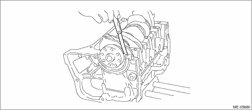
4. Use a thickness gauge to measure the thrust clearance of crankshaft at the #5 crank journal. If clearance exceeds the standard, replace the bearing.
Crankshaft thrust clearance:
Standard:
0.030 — 0.115 mm (0.0012 — 0.0045 in)
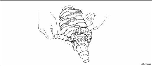
5. Inspect individual crankshaft bearings for signs of flaking, seizure, melting and wear.
6. Measure the oil clearance on each crankshaft bearing using plastigauge. If the measurement value is not within the standard, replace the defective bearing with an undersize one, and as necessary, replace or recondition the crankshaft.
Crankshaft oil clearance:
Standard
#1, #2, #3, #4, #5
0.020 — 0.040 mm (0.0008 — 0.0016 in)