|
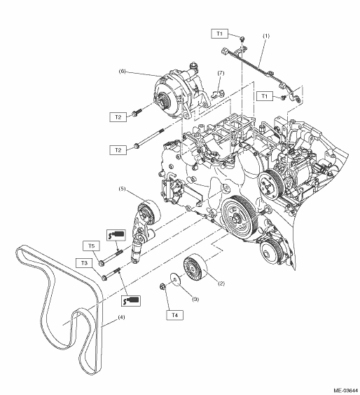
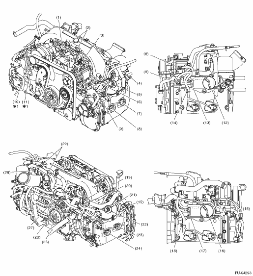
(1) |
Collector cover bracket |
(5) |
V-belt tensioner |
Tightening torque:N·m (kgf-m, ft-lb) | |
|
(2) |
Idler pulley |
(6) |
Generator |
T1: |
6.4 (0.7, 4.7) |
|
(3) |
Idler pulley cover |
(7) |
Generator bracket |
T2: |
25 (2.5, 18.4) |
|
(4) |
V-belt |
T3: |
30 (3.1, 22.1) | ||
|
T4: |
33 (3.4, 24.3) | ||||
|
T5: |
57 (5.8, 42.0) | ||||
|
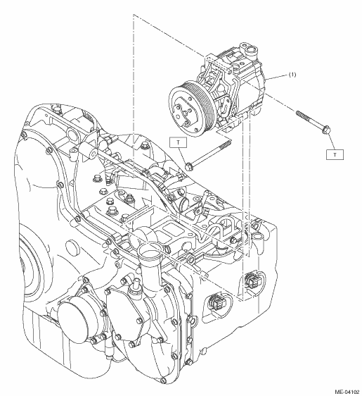
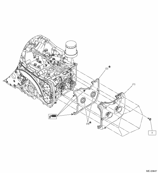
(1) |
A/C compressor |
Tightening torque:N·m (kgf-m, ft-lb) | |||
|
T: |
25 (2.5, 18.4) | ||||
|
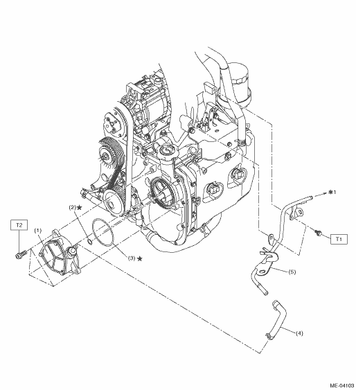
(1) |
Vacuum pump |
(4) |
Vacuum hose |
Tightening torque:N·m (kgf-m, ft-lb) | |
|
(2) |
O-ring |
(5) |
Air by-pass pipe |
T1: |
6.4 (0.7, 4.7) |
|
(3) |
O-ring |
T2: |
19 (1.9, 14.0) | ||
*1: To the brake booster
|
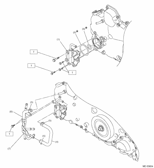
(1) |
Scavenge pump |
(5) |
Clamp |
Tightening torque:N·m (kgf-m, ft-lb) | |
|
(2) |
O-ring |
(6) |
Turbo hose |
T: |
6.4 (0.7, 4.7) |
|
(3) |
O-ring |
(7) |
Turbo pipe |
||
|
(4) |
Turbo hose |
||||
|
(1) |
Rocker cover |
(3) |
Fuel injector gasket |
Tightening torque:N·m (kgf-m, ft-lb) | |
|
(2) |
Rocker cover gasket |
T: |
6.4 (0.7, 4.7) | ||
|
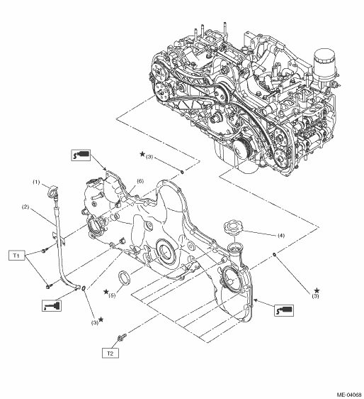
(1) |
Oil level gauge |
(4) |
Oil filler cap |
Tightening torque:N·m (kgf-m, ft-lb) | |
|
(2) |
Oil level gauge guide |
(5) |
Oil seal |
T1: |
6.4 (0.7, 4.7) |
|
(3) |
O-ring |
(6) |
Chain cover |
T2: |
|

|
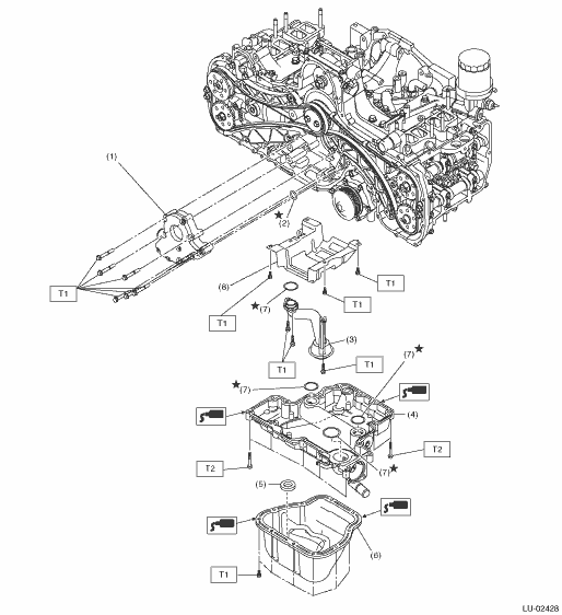
(1) |
Oil pump |
(5) |
Magnet |
Tightening torque:N·m (kgf-m, ft-lb) | |
|
(2) |
O-ring |
(6) |
Oil pan lower |
T1: |
6.4 (0.7, 4.7) |
|
(3) |
Strainer |
(7) |
O-ring |
T2: |
18 (1.8, 13.3) |
|
(4) |
Oil pan upper |
(8) |
Baffle plate |
||
|
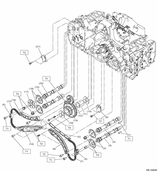
(1) |
Chain guide (sprocket) |
(11) |
Reduction sprocket and gear shaft |
(21) |
Chain tensioner (RH) |
|
(2) |
Intake camshaft (LH) |
(12) |
Fuel pump gear |
||
|
(3) |
Exhaust camshaft (LH) |
(13) |
Reduction sprocket and gear |
Tightening torque:N·m (kgf-m, ft-lb) | |
|
(4) |
Camshaft sprocket (LH) |
(14) |
Chain guide (RH) |
T1: |
6.4 (0.7, 4.7) |
|
(5) |
Chain guide (LH) |
(15) |
Timing chain (RH) |
T2: |
16 (1.6, 11.8) |
|
(6) |
Chain guide (between cams) |
(16) |
Chain tensioner lever (RH) |
T3: |
25 (2.5, 18.4) |
|
(7) |
Timing chain (LH) |
(17) |
Cam shaft plate |
T4: |
|
|
(8) |
Chain tensioner lever (LH) |
(18) |
Camshaft sprocket (RH) |
T5: |
63.7 (6.5, 47.0) |
|
(9) |
Chain tensioner (LH) |
(19) |
Exhaust camshaft (RH) |
||
|
(10) |
Reduction sprocket and gear plate |
(20) |
Intake camshaft (RH) |
||

|
(1) |
Cylinder head (RH) |
(11) |
Intake camshaft cap (Center LH) |
(21) |
Cylinder block (LH) |
|
(2) |
Cylinder head (LH) |
(12) |
Exhaust camshaft cap (Rear LH) |
(22) |
Seal washer |
|
(3) |
Cylinder head gasket (RH) |
(13) |
Exhaust camshaft cap (Center LH) |
||
|
(4) |
Cylinder head gasket (LH) |
(14) |
Front camshaft cap (LH) |
Tightening torque:N·m (kgf-m, ft-lb) | |
|
(5) |
Glow plug |
(15) |
Intake camshaft cap (Rear RH) |
T1: |
6.4 (0.7, 4.7) |
|
(6) |
Intake camshaft (RH) |
(16) |
Intake camshaft cap (Center RH) |
T2: |
11.5 (1.2, 8.5) |
|
(7) |
Exhaust camshaft (RH) |
(17) |
Exhaust camshaft cap (Rear RH) |
T3: |
9.75 (1.0, 7.2) |
|
(8) |
Intake camshaft (LH) |
(18) |
Exhaust camshaft cap (Center RH) |
T4: |
18 (1.8, 13.3) |
|
(9) |
Exhaust camshaft (LH) |
(19) |
Front camshaft cap (RH) |
T5: |
|
|
(10) |
Intake camshaft cap (Rear LH) |
(20) |
Cylinder block (RH) |
||
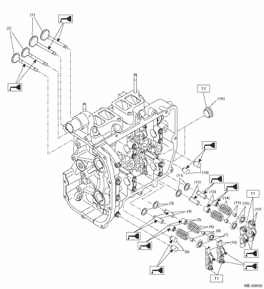
|
(1) |
Intake valve |
(9) |
Rocker arm pivot (exhaust) |
(17) |
Valve rocker (intake) |
|
(2) |
Exhaust valve |
(10) |
Valve rocker (exhaust) |
(18) |
Rocker arm pivot (intake) |
|
(3) |
Valve spring sheet (exhaust) |
(11) |
Valve spring sheet (intake) |
(19) |
Plug |
|
(4) |
Valve guide (exhaust) |
(12) |
Valve guide (intake) |
||
|
(5) |
Stem seal (exhaust) |
(13) |
Stem seal (intake) |
Tightening torque:N·m (kgf-m, ft-lb) | |
|
(6) |
Valve spring (exhaust) |
(14) |
Valve spring (intake) |
T1: |
10 (1.0, 7.4) |
|
(7) |
Valve spring retainer (exhaust) |
(15) |
Valve collet (intake) |
T2: |
60 (6.1, 44.3) |
|
(8) |
Valve collet (exhaust) |
(16) |
Valve spring retainer (intake) |
||
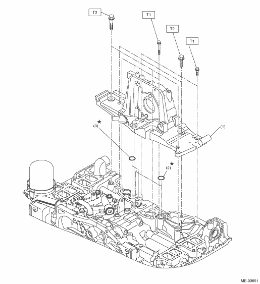
|
(1) |
Generator bracket |
(3) |
O-ring |
Tightening torque:N·m (kgf-m, ft-lb) | |
|
(2) |
O-ring |
T1: |
6.4 (0.7, 4.7) | ||
|
T2: |
33 (3.4, 24.3) | ||||
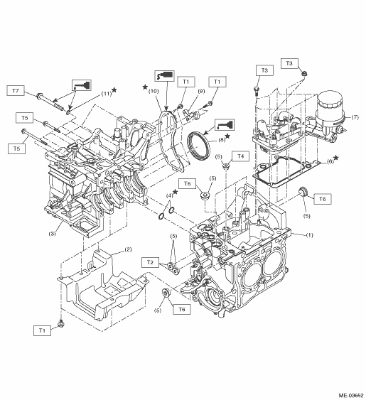
|
(1) |
Cylinder block (LH) |
(7) |
Oil cooler ASSY |
Tightening torque:N·m (kgf-m, ft-lb) | |
|
(2) |
Baffle |
(8) |
Oil seal |
T1: |
6.4 (0.7, 4.7) |
|
(3) |
Cylinder block (RH) |
(9) |
Crankshaft sensor holder |
T2: |
37 (3.8, 27.3) |
|
(4) |
O-ring |
(10) |
Oil separator cover |
T3: |
19 (1.9, 14.0) |
|
(5) |
Plug |
(11) |
Seal washer |
T4: |
23 (2.3, 17.0) |
|
(6) |
Gasket |
T5: |
25 (2.5, 18.4) | ||
|
T6: |
70 (7.1, 51.6) | ||||
|
T7: |
| ||||
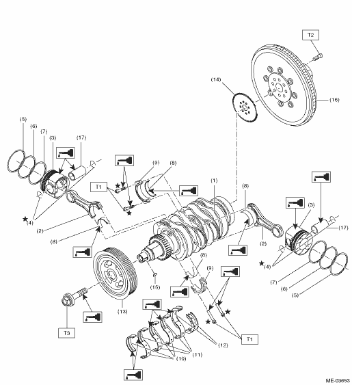
|
(1) |
Crankshaft |
(9) |
Connecting rod cap |
(17) |
Piston pin |
|
(2) |
Connecting rod |
(10) |
Crankshaft bearing #1, #3 |
||
|
(3) |
Piston |
(11) |
Crankshaft bearing #2, #4 |
Tightening torque:N·m (kgf-m, ft-lb) | |
|
(4) |
Snap ring |
(12) |
Crankshaft bearing #5 |
T1: |
|
|
(5) |
Top ring |
(13) |
Crank pulley |
T2: |
|
|
(6) |
Second ring |
(14) |
Crankshaft sensor plate |
T3: |
|
|
(7) |
Oil ring |
(15) |
Woodruff key |
||
|
(8) |
Connecting rod bearing |
(16) |
Flywheel |
||
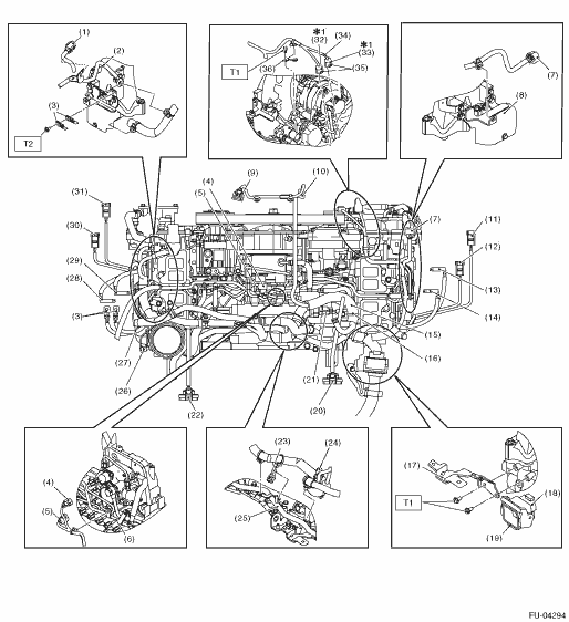
• Structural diagram 1
|
(1) |
Boost control valve |
|
(2) |
Securely install the engine harness clips to the vacuum pipe stay. |
|
(3) |
Manifold absolute pressure and intake air temperature sensor |
|
(4) |
Oil pressure switch |
|
(5) |
Securely install the engine harness clip to the intake manifold protector. |
|
(6) |
Glow docking connector |
|
(7) |
Fuel injector (#4) |
|
(8) |
Fuel injector (#2) |
|
(9) |
Engine coolant temperature sensor |
|
(10) |
Exhaust temperature sensor 1 |
|
(11) |
Exhaust temperature sensor 2 |
|
(12) |
Glow plug (#4) |
|
(13) |
Glow plug (#2) |
|
(14) |
Securely install the engine harness clip to the rocker cover. |
|
(15) |
Camshaft position sensor |
|
(16) |
Glow plug (#1) |
|
(17) |
Glow plug (#3) |
|
(18) |
Securely install the engine harness clip to the rocker cover. |
|
(19) |
EGR control valve |
|
(20) |
Insert the harness connected to the EGR control valve to the underside of the air breather hose. |
|
(21) |
Route the harness connected to the camshaft position sensor under the vacuum hose. |
|
(22) |
Securely install the engine harness clip to the intake manifold protector. |
|
(23) |
Fuel injector (#1) |
|
(24) |
Fuel injector (#3) |
|
(25) |
Body harness |
|
(26) |
Crankshaft position sensor |
|
(27) |
Securely install the engine harness clips to the engine coolant pipe. (2 locations) |
|
(28) |
Throttle position sensor |
|
(29) |
Securely install the engine harness clips to the air breather pipe. |
|
*1: When reusing the engine harness, remove and install the harness and the oil level gauge guide as a set. | |
• Structural diagram 2
|
(1) |
Docking connector (Attach the harness connector securely onto the stay lock.) | |
|
(2) |
By-pass air pipe | |
|
(3) |
Engine ground | |
|
(4) |
Suction control valve | |
|
(5) |
Fuel temperature sensor | |
|
(6) |
Fuel pipe | |
|
(7) |
Camshaft position sensor | |
|
(8) |
Intake manifold protector | |
|
(9) |
Manifold absolute pressure and intake air temperature sensor | |
|
(10) |
Boost control valve | |
|
(11) |
Fuel injector (#1) | |
|
(12) |
Fuel injector (#3) | |
|
(13) |
Glow plug (#1) | |
|
(14) |
Glow plug (#3) | |
|
(15) |
Route the engine harness above the fuel pipe. | |
|
(16) |
Install the engine harness clip to the fuel return pipe stay. | |
|
(17) |
Engine harness stay | |
|
(18) |
Docking connector | |
|
(19) |
Securely install the harness connector to the lock part of the engine harness stay. | |
|
(20) |
EGR control valve | |
|
(21) |
Common rail pressure sensor | |
|
(22) |
Throttle position sensor | |
|
(23) |
Crankshaft position sensor | |
|
(24) |
EGR control valve | |
|
(25) |
Water pipe | |
|
(26) |
Oil pressure switch | |
|
(27) |
Route the engine ground under the engine harness. | |
|
(28) |
Glow plug (#4) | |
|
(29) |
Glow plug (#2) | |
|
(30) |
Fuel injector (#4) | |
|
(31) |
Fuel injector (#2) | |
|
(32) |
Exhaust temperature sensor 1 | |
|
(33) |
Exhaust temperature sensor 2 | |
|
(34) |
Yellow marking | |
|
(35) |
Securely install the harness connector to the stay lock part of the oil level gauge guide. | |
|
(36) |
Install the engine harness stay while pushing the stay against the generator bracket. | |
|
*1: When reusing the engine harness, remove and install the harness and the oil level gauge guide as a set. | ||
|
Tightening torque:N·m (kgf-m, ft-lb) |
||
|
T1: |
6.4 (0.7, 4.7) |
|
|
T2: |
19 (1.9, 14.0) |
|
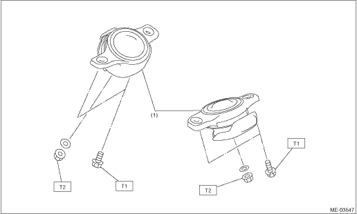
|
(1) |
Front cushion rubber |
Tightening torque:N·m (kgf-m, ft-lb) | |||
|
T1: |
35 (3.6, 25.8) | ||||
|
T2: |
85 (8.7, 62.7) | ||||