1. Install the tumble generator valve assembly onto intake manifold.
NOTE:
Use new O-rings.
Tightening torque:
8.3 N·m (0.8 kgf-m, 6.1 ft-lb)
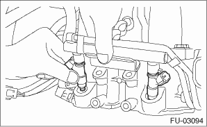
2. Install the fuel injector pipe.
3. Connect fuel hoses to fuel injector pipes on both sides, and secure them with the clamps.
Tightening torque:
1.25 N·m (0.1 kgf-m, 0.9 ft-lb)
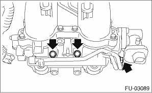
4. Tighten the bolts which secure the fuel injector pipe RH to the lower side of the intake manifold.
Tightening torque:
6.4 N·m (0.7 kgf-m, 4.7 ft-lb)
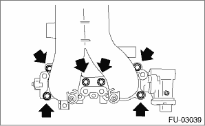
5. Tighten the bolts which secure fuel injector pipe onto intake manifold.
Tightening torque:
6.4 N·m (0.7 kgf-m, 4.7 ft-lb)
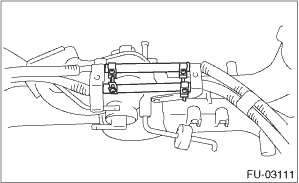
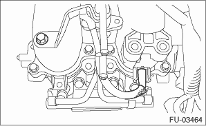
6. Install the fuel injector.
• RH side
• LH side
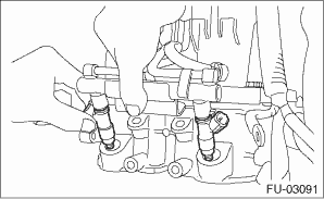
7. Tighten the bolts which secure fuel injector pipe onto intake manifold.
Tightening torque:
19 N·m (1.9 kgf-m, 14.0 ft-lb)
• LH side
• RH side
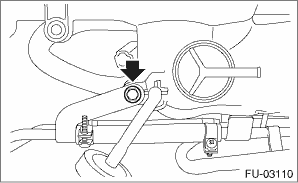
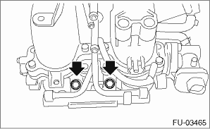
8. Tighten the bolt which holds the fuel injector pipe LH to the front side of the intake manifold, and connect the pressure regulator vacuum hose to the intake manifold.
Tightening torque:
6.4 N·m (0.7 kgf-m, 4.7 ft-lb)
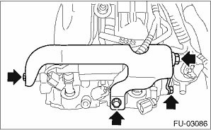
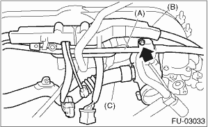
9. Install PCV pipe (A), harness assembly (B) and intake duct (C) to the intake manifold.
Tightening torque:
6.5 N·m (0.7 kgf-m, 4.8 ft-lb)
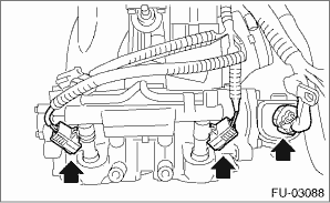
10. Connect the connector to the fuel injector and the tumble generator valve assembly.
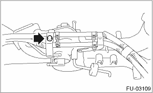
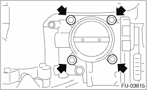
11. Install the throttle body to the intake manifold.
NOTE:
Use new O-rings.
Tightening torque:
8 N·m (0.8 kgf-m, 5.9 ft-lb)
12. Connect the connector to the throttle position sensor.
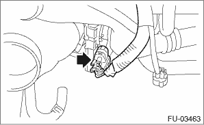
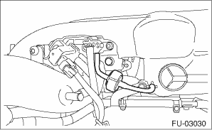
13. Connect the evaporation hose to purge control solenoid valve 2.
NOTE:
Connect the evaporation hose as shown in the figure.
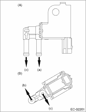
|
(A) |
Purge control solenoid valve 1 |
|
(B) |
Purge control solenoid valve 2 |
|
(a) |
To intake manifold |
|
(b) |
To intake duct |
|
(c) |
To fuel pipe |
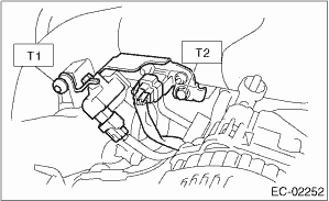
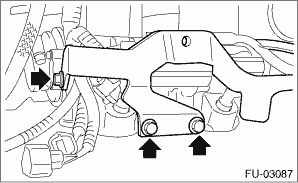
14. Connect the connectors to the wastegate control solenoid valve, manifold absolute pressure sensor and purge control solenoid valve 2, and install the solenoid valve bracket assembly to the intake manifold.
Tightening torque:
T1: 17 N·m (1.7 kgf-m, 12.5 ft-lb)
T2: 19 N·m (1.9 kgf-m, 14.0 ft-lb)
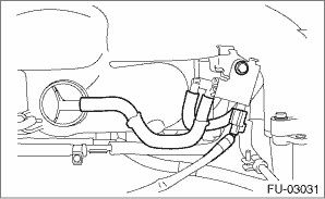
15. Connect the filter assembly.
16. Connect the evaporation hose and the connector to the purge control solenoid valve 1, and install the purge control solenoid valve 1 to the intake manifold.
NOTE:
Connect the evaporation hose as shown in the figure.
|
(A) |
Purge control solenoid valve 1 |
|
(B) |
Purge control solenoid valve 2 |
|
(a) |
To intake manifold |
|
(b) |
To intake duct |
|
(c) |
To fuel pipe |
Tightening torque:
6.4 N·m (0.7 kgf-m, 4.7 ft-lb)
17. Install the fuel pipe protector RH to the intake manifold.
Tightening torque:
19 N·m (1.9 kgf-m, 14.0 ft-lb)
18. Install the fuel pipe protector LH to the intake manifold, and install the engine ground terminal to the fuel pipe protector LH.
Tightening torque:
19 N·m (1.9 kgf-m, 14.0 ft-lb)