NOTE:
Inspection and adjustment of valve clearance should be performed while engine is cold.
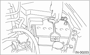
1. Disconnect the ground cable from battery.
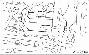
2. Remove the timing belt cover LH.
3. Remove the fuel injector. 
4. When inspecting #1 and #3 cylinders
(1) Disconnect the spark plug cords from spark plugs RH side.
(2) Place a suitable container under the vehicle.
(3) Disconnect the PCV hose from the rocker cover RH.
(4) Remove the bolts, then remove the rocker cover RH.
5. When inspecting #2 and #4 cylinders
(1) Disconnect the spark plug cords from spark plugs LH side.
(2) Place a suitable container under the vehicle.
(3) Disconnect the PCV hose from the rocker cover LH.
(4) Remove the bolts, then remove the rocker cover LH.
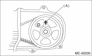
6. Set #1 cylinder piston to top dead center of compression stroke by rotating the crank pulley clockwise using the socket wrench.
NOTE:
When the arrow mark (A) on cam sprocket LH is at the top position, the #1 cylinder piston is at top dead center of the compression stroke.
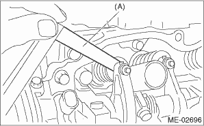
7. Measure #1 cylinder valve clearance by using thickness gauge (A).
NOTE:
• Insert the thickness gauge (A) in as horizontally as possible with respect to the valve stem end face.
• Lift up the vehicle and measure the exhaust valve clearances.
Valve clearance:
Intake
0.20±0.04 mm (0.0079±0.0016 in)
Exhaust
0.25±0.04 mm (0.0098±0.0016 in)
8. If necessary, adjust the valve clearance.
9. Measure the valve clearance in #3, #2 and #4 cylinder in the same measurement procedure as #1 cylinder in this order.
NOTE:
• Be sure to set the cylinder pistons to their respective top dead centers on compression stroke before measuring valve clearances.
• By rotating the crank pulley clockwise every 180° from the state that #1 cylinder piston is on the top dead center of compression stroke, #3, #2 and #4 cylinder pistons come to the top dead center of compression stroke in this order.
10. After inspection, install the related parts in the reverse order of removal.
NOTE:
Use a new rocker cover gasket.