1.CHECK POWER SUPPLY CIRCUIT.
Connect the SDI (Subaru Diagnosis Interface) or general scan tool to data link connector.
|
Does SDI or general scan tool turn ON?
|
|
|
2.CHECK POWER SUPPLY CIRCUIT.
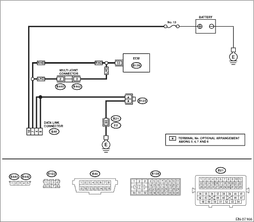
Measure the voltage between data link connector and chassis ground.
Connector & terminal
(B40) No. 16 (+) — Chassis ground (−):
|
Is the voltage 10 V or more?
|
|
Repair the power supply circuit.
NOTE:
In this case, repair the following item:
• Open or ground short circuit of harness between battery and data link connector
• Blown out of fuse (M/B No. 13)
|
3.CHECK HARNESS BETWEEN DATA LINK CONNECTOR AND CHASSIS GROUND.
Measure the resistance of harness between data link connector and chassis ground.
Connector & terminal
(B40) No. 4 — Chassis ground:
(B40) No. 5 — Chassis ground:
|
Is the resistance less than 5 Ω?
|
Repair the poor contact of data link connector.
|
Repair the harness and connector.
NOTE:
In this case, repair the following item:
• Open circuit in harness between data link connector and chassis ground
• Poor contact of coupling connector
|
4.CHECK HARNESS BETWEEN ECM AND DATA LINK CONNECTOR.
1) Turn the ignition switch to OFF.
2) Disconnect the connectors from ECM, VDC CM, power steering CM, airbag CM and body integrated unit.
CAUTION:
When disconnecting the connector from airbag control module, always follow the precautions on AB section. 
3) Measure the resistance of harness between ECM and data link connector.
Connector & terminal
(B135) No. 33 — (B40) No. 7:
|
Is the resistance less than 1 Ω?
|
|
Repair the harness and connector.
NOTE:
In this case, repair the following item:
• Open circuit of harness between ECM and data link connector
• Poor contact of multi-joint connector
|
5.CHECK HARNESS BETWEEN ECM AND DATA LINK CONNECTOR.
Measure the resistance between data link connector and chassis ground.
Connector & terminal
(B40) No. 7 — Chassis ground:
|
Is the resistance 1 MΩ or more?
|
Repair the poor contact of the ECM or data link connector.
|
Repair the ground short circuit of harness between ECM and data link connector.
|