|
Description |
Connector No. |
Terminal No. |
Signal (V) |
Note | ||
|
Ignition SW ON (engine OFF) |
Ignition SW ON (idling) | |||||
|
Crankshaft position sensor |
Signal |
B134 |
44 |
0 |
0 or 5 |
Waveform |
|
Power supply |
B134 |
43 |
5 |
5 |
— | |
|
Ground |
B134 |
63 |
0 |
0 |
— | |
|
Camshaft position sensor |
Signal |
B134 |
45 |
0 |
0 or 5 |
Waveform |
|
Ground |
B134 |
64 |
0 |
0 |
— | |
|
Air flow sensor |
Signal |
B134 |
52 |
— |
1 — 2 |
— |
|
Ground |
B134 |
71 |
0 |
0 |
— | |
|
Intake air temperature sensor (integrated with air flow sensor) |
Signal |
B134 |
53 |
1.9 |
1.9 |
30°C (86°F) |
|
Ground |
B134 |
69 |
0 |
0 |
— | |
|
Engine coolant temperature sensor |
Signal |
B134 |
49 |
1 |
1 |
75°C (167°F) |
|
Ground |
B134 |
67 |
0 |
0 |
— | |
|
Manifold absolute pressure sensor |
Signal |
B134 |
50 |
1 |
1 |
101 kPa |
|
Power supply |
B134 |
62 |
5 |
5 |
— | |
|
Ground |
B135 |
16 |
0 |
0 |
— | |
|
Intake air temperature sensor (integrated with manifold absolute pressure sensor) |
Signal |
B134 |
77 |
1.9 |
1.9 |
30°C (86°F) |
|
Ground |
B135 |
16 |
0 |
0 |
— | |
|
Fuel temperature sensor |
Signal |
B134 |
48 |
1.2 |
1.2 |
50°C (122°F) |
|
Ground |
B134 |
68 |
0 |
0 |
— | |
|
Common rail pressure sensor |
Signal |
B134 |
46 |
— |
1.4 |
25 MPa |
|
Power supply |
B134 |
42 |
5 |
5 |
— | |
|
Ground |
B134 |
76 |
0 |
0 |
— | |
|
Exhaust gas temperature sensor 1 |
Signal |
B134 |
54 |
4.4 |
4.4 |
200°C (392°F) |
|
Ground |
B134 |
72 |
0 |
0 |
— | |
|
Exhaust gas temperature sensor 2 |
Signal |
B134 |
55 |
4.4 |
4.4 |
200°C (392°F) |
|
Ground |
B134 |
72 |
0 |
0 |
— | |
|
DPF pressure difference sensor |
Signal |
B134 |
56 |
0.54 |
0.54 |
1 kPa |
|
Power supply |
B134 |
42 |
5 |
5 |
— | |
|
Ground |
B134 |
72 |
0 |
0 |
— | |
|
Accelerator pedal position sensor |
Main signal |
B135 |
39 |
0.57 — 0.77 |
0.57 — 0.77 |
— |
|
Main power supply |
B135 |
29 |
5 |
5 |
— | |
|
Main ground |
B135 |
27 |
0 |
0 |
— | |
|
Sub signal |
B135 |
28 |
0.57 — 0.79 |
0.57 — 0.79 |
— | |
|
Sub power supply |
B134 |
42 |
5 |
5 |
— | |
|
Sub ground |
B135 |
38 |
0 |
0 |
— | |
|
Electronic throttle control |
Sensor signal |
B135 |
36 |
3 — 4.6 |
3 — 4.6 |
— |
|
Power supply |
B134 |
61 |
5 |
5 |
— | |
|
Ground |
B134 |
70 |
0 |
0 |
— | |
|
Motor (+) |
B135 |
30 |
Duty waveform |
Duty waveform |
Operation frequency: 500 Hz | |
|
Motor (−) |
B135 |
12 |
Duty waveform |
Duty waveform |
Operation frequency: 500 Hz | |
|
EGR control valve |
Sensor signal |
B134 |
51 |
1.2 |
2 — 3 |
— |
|
Power supply |
B134 |
57 |
5 |
5 |
— | |
|
Ground |
B134 |
66 |
0 |
0 |
— | |
|
Motor (+) |
B134 |
3 |
Duty waveform |
Duty waveform |
Operation frequency: 500 Hz | |
|
Motor (−) |
B134 |
2 |
Duty waveform |
Duty waveform |
Operation frequency: 500 Hz | |
|
Suction control valve |
Operation output |
B134 |
26 |
Duty waveform |
Duty waveform |
Operation frequency: 250 Hz |
|
Power supply |
B134 |
5 |
Duty waveform |
Duty waveform |
Operation frequency: 250 Hz | |
|
Boost control valve |
Operation output |
B134 |
1 |
10 — 13 |
Duty waveform |
Operation frequency: 500 Hz |
|
Fuel injector |
Operation power supply 1 |
B134 |
21 |
4 — 7 |
0 — 90 |
— |
|
Operation power supply 2 |
B134 |
20 |
4 — 7 |
0 — 90 |
— | |
|
#1 — 1 |
B134 |
39 |
4 — 7 |
0 — 90 |
Waveform | |
|
#1 — 2 |
B134 |
40 |
4 — 7 |
0 — 90 |
Waveform | |
|
#2 — 1 |
B134 |
37 |
4 — 7 |
0 — 90 |
Waveform | |
|
#2 — 2 |
B134 |
38 |
4 — 7 |
0 — 90 |
Waveform | |
|
#3 — 1 |
B134 |
18 |
4 — 7 |
0 — 90 |
Waveform | |
|
#3 — 2 |
B134 |
19 |
4 — 7 |
0 — 90 |
Waveform | |
|
#4 — 1 |
B134 |
16 |
4 — 7 |
0 — 90 |
Waveform | |
|
#4 — 2 |
B134 |
17 |
4 — 7 |
0 — 90 |
Waveform | |
|
Shield |
B134 |
65 |
0 |
0 |
— | |
|
Generator control |
B134 |
22 |
0 — 6.5 |
0 — 6.5 |
— | |
|
Engine speed signal |
B135 |
11 |
0 |
0 — 14 |
Waveform | |
|
Malfunction indicator light |
B134 |
13 |
0 |
12 — 14 |
— | |
|
Glow voltage monitor |
B134 |
73 |
When glow activates: 10 — 13 When glow does not activates: 0 |
When glow activates: 12 — 14 When glow does not activates: 0 |
— | |
|
Glow relay control |
B134 |
34 |
When glow activates: 10 — 13 When glow does not activates: 0 |
When glow activates: 12 — 14 When glow does not activates: 0 |
— | |
|
Main relay control |
B135 |
14 |
0 |
0 |
— | |
|
Sub fuel pump relay control |
B134 |
11 |
10 — 13 |
0 |
— | |
|
Radiator fan relay 1 control |
B134 |
24 |
ON: 0.5 or less OFF: 10 — 13 |
ON: 0.5 or less OFF: 12 — 14 |
— | |
|
Radiator fan relay 2 control |
B134 |
25 |
ON: 0.5 or less OFF: 10 — 13 |
ON: 0.5 or less OFF: 12 — 14 |
— | |
|
A/C relay control |
B134 |
10 |
ON: 0.5 or less OFF: 10 — 13 |
ON: 0.5 or less OFF: 12 — 14 |
— | |
|
A/C pressure switch |
B135 |
6 |
ON: 0 OFF: 10 — 13 |
ON: 0 OFF: 12 — 14 |
— | |
|
Starter relay control |
B134 |
36 |
0 |
0 |
Model with push button start, with clutch pedal depressed except when cranking: 10 — 14 | |
|
Starter cut relay control |
B134 |
12 |
0 |
0 |
Model with push button start, when cranking: 8 — 14 | |
|
Accessory cut request |
B134 |
35 |
10 — 13 |
12 — 14 |
Model with push button start | |
|
Ignition switch |
B135 |
10 |
10 — 13 |
12 — 14 |
— | |
|
Delivery (test) mode switch |
B135 |
7 |
10 — 13 |
12 — 14 |
When delivery (test) mode connector connected: 0 | |
|
Neutral position switch |
B135 |
21 |
ON: 0.5 or less OFF: 10 — 13 |
ON: 0.5 or less OFF: 12 — 14 |
Switch is ON when shift position is in neutral. | |
|
Clutch switch |
B134 |
28 |
When clutch pedal is depressed: 0 When clutch pedal is released: 10 — 13 |
When clutch pedal is depressed: 0 When clutch pedal is released: 12 — 14 |
— | |
|
Brake switch 1 |
B135 |
19 |
When brake pedal is depressed: 0 When brake pedal is released: 10 — 13 |
When brake pedal is depressed: 0 When brake pedal is released: 12 — 14 |
— | |
|
Brake switch 2 |
B135 |
18 |
When brake pedal is depressed: 10 — 13 When brake pedal is released: 0 |
When brake pedal is depressed: 12 — 14 When brake pedal is released: 0 |
— | |
|
Handle switch |
B135 |
8 |
0 |
0 |
RHD model | |
|
Starter switch |
B134 |
27 |
0 |
0 |
Model with push button start Cranking: waveform | |
|
Starter switch 2 |
B135 |
20 |
0 |
0 |
Cranking: 8 — 14 | |
|
Clutch start switch |
B134 |
7 |
When clutch pedal is depressed: 10 — 13 When clutch pedal is released: 0 |
When clutch pedal is depressed: 12 — 14 When clutch pedal is released: 0 |
Model with push button start | |
|
Cruise control switch |
Main switch |
B134 |
29 |
ON: 0 OFF: 10 — 13 |
ON: 0 OFF: 12 — 14 |
— |
|
Command switch |
B135 |
17 |
When operating nothing: 3.5 — 4.5 When operating RES/ACC: 2.5 — 3.5 When operating SET/COAST: 0.5 — 1.5 When operating CANCEL: 0 — 0.5 |
When operating nothing: 3.5 — 4.5 When operating RES/ACC: 2.5 — 3.5 When operating SET/COAST: 0.5 — 1.5 When operating CANCEL: 0 — 0.5 |
— | |
|
CAN communication |
HIGH |
B135 |
24 |
— |
— |
Waveform |
|
LOW |
B135 |
35 |
— |
— |
Waveform | |
|
Immobilizer communication |
B135 |
5 |
— |
— |
— | |
|
SSM/GST communication line |
B135 |
33 |
— |
— |
— | |
|
Control module power supply |
B135 |
3 |
10 — 13 |
12 — 14 |
— | |
|
B135 |
2 |
10 — 13 |
12 — 14 |
— | ||
|
Back-up power supply |
B135 |
1 |
10 — 13 |
12 — 14 |
— | |
|
Ground (power supply) |
B134 |
41 |
0 |
0 |
— | |
|
B134 |
80 |
0 |
0 |
— | ||
|
B134 |
81 |
0 |
0 |
— | ||
|
Ground (control system) |
B135 |
13 |
0 |
0 |
— | |
|
B135 |
32 |
0 |
0 |
— | ||
|
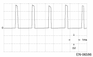
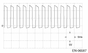
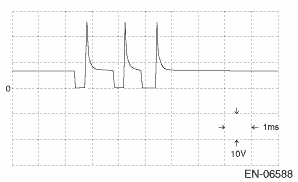
Input/output name |
Measuring condition |
Waveform |
|
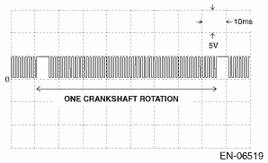
1. Crankshaft position sensor |
At idling |
|
|
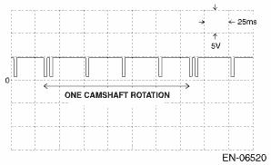
2. Camshaft position sensor |
At idling |
|
|
3. EGR control valve |
At idling |
|
|
4. Suction control valve |
At idling |
|
|
5. Fuel injector |
At idling |
|
• Model without push button start

• Model with push button start
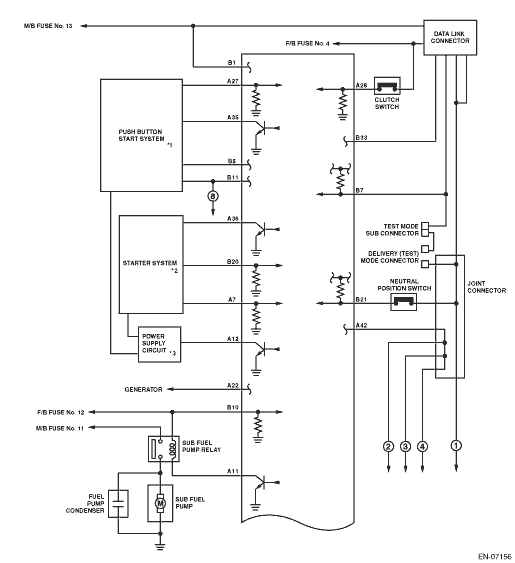
|
*1 |
Refer to “Push Button Start System” in WI section. |
|
*2 |
Refer to “Starter System” in WI section. |
|
*3 |
Refer to “Power Supply Circuit” in WI section. |