Perform the Inspection Mode for DTC shown in the following table.
For DTC not listed in the table, refer to the item on the drive cycle. 
NOTE:
Perform the Inspection Mode two times for * marked DTC, or three times for ** marked DTC in the following table.
|
DTC |
Item |
|
*P0016 |
Crankshaft Position - Camshaft Position Correlation (Bank1) |
|
P0046 |
Wastegate Valve Circuit (Low) |
|
P0088 |
Fuel Pressure Abnormal (High) |
|
**P0089 |
Pressure Limiter Valve Opening Problem |
|
P0093 |
Fuel System Abnormal (Leak) |
|
P0097 |
Intake Air Temperature Sensor #2 Circuit (Low) |
|
P0098 |
Intake Air Temperature Sensor #2 Circuit (High) |
|
P0102 |
Mass or Volume Air Flow Circuit Low Input |
|
P0103 |
Mass or Volume Air Flow Circuit High Input |
|
P0107 |
Manifold Absolute Pressure/Barometric Pressure Circuit Low Input |
|
P0108 |
Manifold Absolute Pressure/Barometric Pressure Circuit High Input |
|
P0112 |
Intake Air Temperature Sensor 1 Circuit Low |
|
P0113 |
Intake Air Temperature Sensor 1 Circuit High |
|
P0117 |
Engine Coolant Temperature Circuit Low |
|
P0118 |
Engine Coolant Temperature Circuit High |
|
P0122 |
Throttle/Pedal Position Sensor/Switch “A” Circuit Low |
|
P0123 |
Throttle/Pedal Position Sensor/Switch “A” Circuit High |
|
P0182 |
Fuel Temperature Sensor “A” Circuit Low Input |
|
P0183 |
Fuel Temperature Sensor “A” Circuit High Input |
|
*P0191 |
Fuel Pressure Sensor Performance |
|
P0192 |
Fuel Rail Pressure Sensor Circuit Low |
|
P0193 |
Fuel Rail Pressure Sensor Circuit High |
|
P0201 |
Cylinder 1 - Injector Circuit |
|
P0202 |
Cylinder 2 - Injector Circuit |
|
P0203 |
Cylinder 3 - Injector Circuit |
|
P0204 |
Cylinder 4 - Injector Circuit |
|
P0219 |
Engine Overrunning Failure |
|
*P0301 |
Cylinder 1 Misfire Detected |
|
*P0302 |
Cylinder 2 Misfire Detected |
|
*P0303 |
Cylinder 3 Misfire Detected |
|
*P0304 |
Cylinder 4 Misfire Detected |
|
P0335 |
Crankshaft Position Sensor “A” Circuit |
|
*P0336 |
Crankshaft Position Sensor “A” Circuit Range/Performance |
|
P0340 |
Camshaft Position Sensor A Circuit |
|
*P0341 |
Camshaft Position Sensor “A” Circuit Range/Performance (Bank 1 or Single Sensor) |
|
*P0403 |
EGR System Failure (Circuit Duty) |
|
*P0404 |
EGR Operation Circuit Abnormal |
|
P0405 |
EGR Position Sensor Circuit (Low) |
|
P0406 |
EGR Position Sensor Circuit (High) |
|
*P0409 |
EGR Position Sensor Performance |
|
*P0462 |
Fuel Level Sensor “A” Circuit Low |
|
*P0463 |
Fuel Level Sensor “A” Circuit High |
|
P0500 |
Vehicle Speed Sensor “A” |
|
P0512 |
Starter Request Circuit |
|
P0545 |
Exhaust Gas Temperature Sensor Circuit Malfunction (Low Input) |
|
*P0546 |
Exhaust Gas Temperature Sensor Circuit Malfunction (High Input) |
|
P0600 |
Serial Communication Link |
|
*P0604 |
Internal Control Module Random Access Memory (RAM) Error |
|
P0605 |
Internal Control Module Read Only Memory (ROM) Error |
|
P0606 |
Micro-Computer (CPU Failure) |
|
P0628 |
Suction Control Valve Circuit (Ground Short) |
|
P0629 |
Suction Control Valve Circuit (Battery Short) |
|
*P0638 |
Throttle Actuator Control Range/Performance (Bank 1) |
|
P1201 |
Injector Code Failure (Not Written) |
|
P1202 |
Injector Code Data Abnormal |
|
P1203 |
Injector Code Input Failure |
|
P1213 |
Injector Driver (Low Charge) |
|
P1214 |
Injector Driver (Over Charge) |
|
*P1232 |
Fuel Pump Malfunction |
|
P1233 |
Fuel Pressure Abnormal (Fuel Pump Failure 1) |
|
P1234 |
Fuel Pressure Abnormal (Fuel Pump Failure 2) |
|
*P1380 |
Glow Relay Circuit (Low) |
|
*P1382 |
Glow Relay Circuit (High) |
|
*P1466 |
DPF Substrate Damaged |
|
*P1467 |
Ash Overfill |
|
*P1468 |
Oil Dilution |
|
*P1469 |
DPF Limp-home Mode |
|
P1472 |
DPF Inlet/Outlet Pressure Deviation Sensor (Low) |
|
P1473 |
DPF Inlet/Outlet Pressure Deviation Sensor (High) |
|
P1519 |
Starter SW 2 System Circuit (OFF) |
|
P1520 |
Starter SW 2 System Circuit (ON) |
|
P1607 |
Monitoring Circuit Abnormal |
|
P1616 |
Starter Cut Relay System Circuit (Low) |
|
P2032 |
Exhaust Temperature Sensor2 (Low) |
|
*P2033 |
Exhaust Temperature Sensor2 (High) |
|
*P2101 |
Throttle Actuator Control Motor Circuit Range/Performance |
|
P2122 |
Throttle/Pedal Position Sensor/Switch “D” Circuit Low Input |
|
P2123 |
Throttle/Pedal Position Sensor/Switch “D” Circuit High Input |
|
P2127 |
Throttle/Pedal Position Sensor/Switch “E” Circuit Low Input |
|
P2128 |
Throttle/Pedal Position Sensor/Switch “E” Circuit High Input |
|
P2138 |
Throttle/Pedal Position Sensor/Switch “D”/“E” Voltage Correlation |
|
P2146 |
Fuel Injector Power Supply A Open Circuit |
|
P2147 |
Injector Driver (Ground Short) |
|
P2148 |
Injector Driver (Battery Short) |
|
P2149 |
Fuel Injector Power Supply B Open Circuit |
|
P2228 |
Barometric Pressure Circuit Low |
|
P2229 |
Barometric Pressure Circuit High |
|
*P2413 |
EGR Valve Sticks |
|
*P2633 |
Fuel Pump “B” Control Circuit Low |
|
*P2634 |
Fuel Pump “B” Control Circuit High |
|
P2635 |
Suction Control Valve Sticks |
1. PREPARATION FOR THE INSPECTION MODE
Check that the battery voltage is 12 V or more and fuel remains approx. half [20 — 40 L (5.3 — 10.6 US gal, 4.4 — 8.8 Imp gal)].
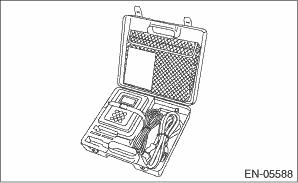
1. Prepare the Subaru Select Monitor kit.
2. Prepare PC with Subaru Select Monitor installed.
3. Connect the USB cable to SDI (Subaru Diagnosis Interface) and USB port on the personal computer (dedicated port for the Subaru Select Monitor).
NOTE:
The dedicated port for the Subaru Select Monitor means the USB port which was used to install the Subaru Select Monitor.
4. Connect the diagnosis cable to SDI.
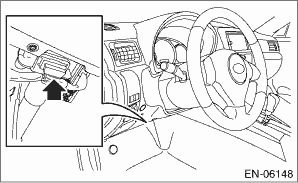
5. Connect SDI to data link connector located in the lower portion of the instrument panel (on the driver’s side).
CAUTION:
Do not connect any scan tools except Subaru Select Monitor or general scan tool.
6. Start the PC.
7. Turn the ignition switch to ON (engine OFF) and run the “PC application for Subaru Select Monitor”.
8. Make sure that no DTC remains after clearing memory.
9. Start the engine and warm up engine until coolant temperature is higher than 60°C (140°F).
NOTE:
For detailed operation procedures, refer to “READ CURRENT DATA FOR ENGINE”.
10. Idle the engine for 60 seconds or more.
11. Turn the ignition switch to OFF, and wait for 10 seconds or more before turning the ignition switch to ON.
NOTE:
When the «Communication error has occurred.» display screen appears, click the [OK] button. When the «Do you want to save the data state immediately preceding the communication error?» display screen appears, click the [NO] button. The screen will return to the «System Selection Menu» display screen.
12. Read the temporary diagnostic code of DTC using Subaru Select Monitor.
13. If the DTC is displayed, perform the diagnosis using “Diagnostic Procedure with Diagnostic Trouble Code (DTC)”. If the DTC is not displayed, finish the diagnosis.
NOTE:
• For detailed operation procedures, refer to “PC application help for Subaru Select Monitor”.
• For details concerning DTC, refer to “List of Diagnostic Trouble Code (DTC)”.
1. Connect the general scan tool to data link connector located in the lower portion of the instrument panel (on the driver’s side).
CAUTION:
Do not connect any scan tools except Subaru Select Monitor or general scan tool.
2. Make sure that no DTC remains after clearing memory.
3. Start the engine and warm up engine until coolant temperature is higher than 60°C (140°F).
4. Idle the engine for 60 seconds or more.
5. Turn the ignition switch to OFF, and wait for 10 seconds or more before turning the ignition switch to ON.
6. Read DTC by performing the MODE $07 using the general scan tool.
7. If the DTC is displayed, perform the diagnosis using “Diagnostic Procedure with Diagnostic Trouble Code (DTC)”. If the DTC is not displayed, finish the diagnosis.
NOTE:
• For detailed operation procedures, refer to the general scan tool operation manual.
• For details concerning DTC, refer to “List of Diagnostic Trouble Code (DTC)”.