1. HOW TO USE SUBARU SELECT MONITOR
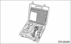
1. Prepare the Subaru Select Monitor kit. 
2. Prepare PC with Subaru Select Monitor installed.
3. Connect the USB cable to SDI (Subaru Diagnosis Interface) and USB port on the personal computer (dedicated port for the Subaru Select Monitor).
NOTE:
The dedicated port for the Subaru Select Monitor means the USB port which was used to install the Subaru Select Monitor.
4. Connect the diagnosis cable to SDI.
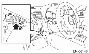
5. Connect SDI to data link connector located in the lower portion of the instrument panel (on the driver’s side).
CAUTION:
Do not connect any scan tools except Subaru Select Monitor or general scan tool.
6. Start the PC.
7. Turn the ignition switch to ON (engine OFF) and run the “PC application for Subaru Select Monitor”.
8. Call up DTC and data, then record them.
NOTE:
For detailed operation procedures, refer to “PC application help for Subaru Select Monitor”.
2. READ CURRENT DATA FOR ENGINE (NORMAL MODE)
1. On «Main Menu» display, select {Each System Check}.
2. On «System Selection Menu» display, select {Engine Control System}.
3. Click the [OK] button after the information of engine type has been displayed.
4. On «Engine Diagnosis» display, select {Current Data Display & Save}.
5. On «Current Data Display & Save» display, select {Normal sampling}.
6. Using the scroll key, scroll the display screen up or down until the desired data is shown.
• A list of the support data is shown in the following table.
|
Contents |
Display |
Unit of measure |
Note (at idling) |
|
Engine coolant temperature signal |
Coolant Temp. |
°C or °F |
80 — 100°C |
|
Intake manifold absolute pressure |
Mani. Absolute Pressure |
kPa, mmHg, inHg or psig |
70 — 110 kPa |
|
Engine speed signal |
Engine Speed |
rpm |
800 rpm |
|
Meter vehicle speed signal |
Vehicle Speed |
km/h or MPH |
0 km/h |
|
Intake air temperature signal (intake manifold) |
Intake Air Temp. |
°C or °F |
20 — 80°C |
|
Intake air amount |
Mass Air Flow |
g/s or lb/m |
5 — 12 g/s |
|
Throttle opening angle signal |
Throttle Opening Angle |
% |
70 — 80 % |
|
Battery voltage |
Battery Voltage |
V |
12 — 15 V |
|
Mass air flow voltage |
Air Flow Sensor Voltage |
V |
1 — 2 V |
|
Atmospheric pressure |
Atmosphere Pressure |
kPa, mmHg, inHg or psig |
(Atmospheric pressure) |
|
Acceleration opening angle signal |
Accel. Opening Angle |
% |
0% |
|
Fuel temperature signal |
Fuel Temp. |
°C or °F |
20 — 80°C |
|
Primary supercharged pressure control signal |
Primary Control |
% |
30 — 60% |
|
Generator duty ratio |
ALT Duty |
% |
0 — 100% |
|
Throttle motor duty ratio |
Throttle Motor Duty |
% |
5 — 25% |
|
Main throttle sensor voltage |
Main-Throttle Sensor |
V |
3 — 4.6 V |
|
Sub accelerator sensor voltage |
Sub-Accelerator Sensor |
V |
0.57 — 0.79 V |
|
Main acceleration sensor voltage |
Main-Accelerator Sensor |
V |
0.57 — 0.77 V |
|
Memory vehicle speed |
Memorized Cruise Speed |
km/h or MPH |
— |
|
Main Injection Period |
Main Injection Period |
°CA |
−7 — 3°CA |
|
Final Injection Amount |
Final Injection Amount |
mm3/st |
3 — 10 mm3/st |
|
Number of Times Injected |
Number of Times Injected |
— |
2 — 3 |
|
Target intake manifold pressure |
Target Intake Manifold Pressure |
kPa |
70 — 110 kPa |
|
Target intake air amount |
Target Intake Air Amount |
mg/cyl |
300 — 400 mg/cyl |
|
Intake air amount |
Mass Air Flow |
mg/cyl |
300 — 400 mg/cyl |
|
Target EGR Valve Opening Angle |
Target EGR Valve Opening Angle |
deg |
20 — 40 deg |
|
EGR Valve Opening Angle |
EGR Valve Opening Angle |
deg |
20 — 40 deg |
|
EGR duty ratio |
EGR Duty |
% |
0 — 30% |
|
Target Common Rail Pressure |
Target Common Rail Pressure |
MPa |
20 — 30 MPa |
|
Common rail pressure |
Common rail pressure |
MPa |
20 — 30 MPa |
|
Intake air temperature signal (air flow sensor) |
Intake Air Temperature |
°C or °F |
20 — 60°C |
|
Target engine speed |
Target engine speed |
rpm |
800 rpm |
|
Boost Pressure Feedback |
Boost Pressure Feedback |
% |
0% |
|
Electric power steering current value |
Electric Power Steering Current Value |
A |
0A |
|
Target Fuel Pump Current |
Target Fuel Pump Current |
mA |
1500 — 2000 mA |
|
Actual Fuel Pump Current |
Actual Fuel Pump Current |
mA |
1500 — 2000 mA |
|
Mileage after Injector Learning |
Mileage after Injector Learning |
km or mile |
— |
|
Mileage after Injector Replacement |
Mileage after Injector Replacement |
km or mile |
— |
|
Interior heater |
Interior heater |
Steps |
— |
|
Cylinder #1 quantity correction value |
Cylinder #1 quantity correction value |
ms |
−0.4 — 0.4 ms |
|
Cylinder #2 quantity correction value |
Cylinder #2 quantity correction value |
ms |
−0.4 — 0.4 ms |
|
Cylinder #3 quantity correction value |
Cylinder #3 quantity correction value |
ms |
−0.4 — 0.4 ms |
|
Cylinder #4 quantity correction value |
Cylinder #4 quantity correction value |
ms |
−0.4 — 0.4 ms |
|
Delivery (test) mode terminal |
Test Mode Signal |
— |
OFF |
|
D-check Require Flag |
D-check Require Flag |
— |
OFF |
|
Delivery (test) mode terminal |
Delivery Mode Connector (Test Mode Connector) |
— |
OFF |
|
Neutral position switch signal |
Neutral Position Switch |
— |
ON |
|
Soft idle switch signal |
Idle Switch Signal |
— |
ON |
|
Ignition switch signal |
Ignition Switch |
— |
ON |
|
Air conditioning switch signal |
A/C Switch |
— |
OFF (when OFF) |
|
Starter switch signal |
Starter Switch |
— |
OFF |
|
Crankshaft position sensor signal |
Crankshaft Position Sig. |
— |
ON |
|
Camshaft position sensor signal |
Camshaft Position Sig. |
— |
ON |
|
Rear defogger switch signal |
Rear Defogger SW |
— |
OFF (when OFF) |
|
Blower fan switch signal |
Blower Fan SW |
— |
OFF (when OFF) |
|
Light switch signal |
Light Switch |
— |
OFF (when OFF) |
|
Wiper switch signal |
Wiper Switch |
— |
OFF (when OFF) |
|
Air conditioner compressor relay output signal |
A/C Compressor Signal |
— |
OFF (when OFF) |
|
Radiator fan relay 1 signal |
Radiator Fan Relay #1 |
— |
OFF (when OFF) |
|
Radiator fan relay 2 signal |
Radiator Fan Relay #2 |
— |
OFF (when OFF) |
|
Vehicle dynamics control (VDC) torque down prohibition output |
Ban of Torque Down |
— |
ON |
|
Vehicle dynamics control (VDC) torque down demand |
Request Torque Down VDC |
— |
OFF |
|
Clutch switch signal |
Clutch Switch |
— |
OFF (when OFF) |
|
Stop light switch signal |
Stop lamp SW |
— |
OFF (when OFF) |
|
SET/COAST switch signal |
SET/COAST Switch |
— |
OFF (when OFF) |
|
RESUME/ACCEL switch signal |
RESUME/ACCEL Switch |
— |
OFF (when OFF) |
|
Brake switch signal |
Brake Switch |
— |
OFF (when OFF) |
|
Cruise control main switch signal |
Main Switch |
— |
OFF (when OFF) |
|
Body integrated unit data reception |
Body Int. Unit Data |
— |
ON |
|
Body integrated unit counter update |
Body Int. Unit Count |
— |
ON |
|
Cruise control cancel switch signal |
CC Cancel SW |
— |
OFF (when OFF) |
|
Malfunction indicator light signal |
MIL On Flag |
— |
Light OFF |
|
Boost Pressure Control Mode |
Boost Pressure Control Mode |
— |
Open |
|
EGR Control Mode |
EGR Control Mode |
— |
Feedback |
|
Glow relay signal |
Glow Relay |
— |
OFF |
|
Sub fuel pump relay signal |
Sub Fuel Pump Relay |
— |
ON |
|
Fuel Pump Learning |
Fuel Pump Learning |
— |
Completed |
|
Injector learning |
Injector Learning |
— |
Completed |
|
EGR Learning |
EGR Learning |
— |
Completed |
|
Fuel Cut Request |
Fuel Cut Request |
— |
Without Request |
|
Fuel Pump Mode |
Fuel Pump Mode |
— |
Feedback |
|
Clutch Switch for Smart |
Clutch Switch for Smart |
— |
OFF |
|
DPF Regeneration |
DPF Regeneration |
— |
Regeneration not in progress |
|
Cumulative ash ratio |
Cumulative ash ratio |
% |
0 — 100% |
|
Deviation between DPF inlet and outlet pressure |
Deviation between DPF inlet and outlet pressure |
kPa |
0 — 3 kPa |
|
Exhaust Gas Temperature at Catalyst Inlet |
Exhaust Gas Temperature at Catalyst Inlet |
°C |
100 — 300°C |
|
Exhaust Gas Temperature at DPF Inlet |
Exhaust Gas Temperature at DPF Inlet |
°C |
100 — 300°C |
|
Estimated Catalyst Temperature |
Estimated Catalyst Temperature |
°C |
100 — 300°C |
|
Estimated DPF Temperature |
Estimated DPF Temperature |
°C |
100 — 300°C |
|
Soot Accumulation Ratio |
Soot Accumulation Ratio |
% |
0 — 100% |
|
Oil Dilution Ratio |
Oil Dilution Ratio |
% |
0 — 15% |
|
Accumulated over-rev count (5,900 rpm or more) |
Accumulated count of over-rev instance (very high RPM) |
time |
0 |
|
Accumulated over-rev count (5,500 rpm or more) |
Accumulated count of over-rev instance (high RPM) |
time |
0 |
|
Actual Common Rail Pressure (Time Synchronized) |
Actual Common Rail Pressure (Time Synchronized) |
MPa |
20 — 30 MPa |
|
Estimated distance to oil change |
Estimated distance to oil change |
km |
— |
|
Running distance after last regeneration |
Running distance after last regeneration |
km |
— |
|
DPF regeneration count |
DPF regeneration count |
time |
— |
|
Marginal quantity final learning value 1 _ 1 |
Marginal Q (quantity) Final learning Value 1_1 |
ms |
−0.3 — 0.3 ms |
|
Marginal quantity final learning value 1_2 |
Marginal Q (quantity) Final learning Value 1_2 |
ms |
−0.3 — 0.3 ms |
|
Marginal quantity final learning value 1_3 |
Marginal Q (quantity) Final learning Value 1_3 |
ms |
−0.3 — 0.3 ms |
|
Marginal quantity final learning value 1_4 |
Marginal Q (quantity) Final learning Value 1_4 |
ms |
−0.3 — 0.3 ms |
|
Marginal quantity final learning value 2_1 |
Marginal Q (quantity) Final learning Value 2_1 |
ms |
−0.3 — 0.3 ms |
|
Marginal quantity final learning value 2_2 |
Marginal Q (quantity) Final learning Value 2_2 |
ms |
−0.3 — 0.3 ms |
|
Marginal quantity final learning value 2_3 |
Marginal Q (quantity) Final learning Value 2_3 |
ms |
−0.3 — 0.3 ms |
|
Marginal quantity final learning value 2_4 |
Marginal Q (quantity) Final learning Value 2_4 |
ms |
−0.3 — 0.3 ms |
|
Marginal quantity final learning value 3_1 |
Marginal Q (quantity) Final learning Value 3_1 |
ms |
−0.3 — 0.3 ms |
|
Marginal quantity final learning value 3_2 |
Marginal Q (quantity) Final learning Value 3_2 |
ms |
−0.3 — 0.3 ms |
|
Marginal quantity final learning value 3_3 |
Marginal Q (quantity) Final learning Value 3_3 |
ms |
−0.3 — 0.3 ms |
|
Marginal quantity final learning value 3_4 |
Marginal Q (quantity) Final learning Value 3_4 |
ms |
−0.3 — 0.3 ms |
|
Marginal quantity final learning value 4_1 |
Marginal Q (quantity) Final learning Value 4_1 |
ms |
−0.3 — 0.3 ms |
|
Marginal quantity final learning value 4_2 |
Marginal Q (quantity) Final learning Value 4_2 |
ms |
−0.3 — 0.3 ms |
|
Marginal quantity final learning value 4_3 |
Marginal Q (quantity) Final learning Value 4_3 |
ms |
−0.3 — 0.3 ms |
|
Marginal quantity final learning value 4_4 |
Marginal Q (quantity) Final learning Value 4_4 |
ms |
−0.3 — 0.3 ms |
|
Marginal quantity final learning value 5_1 |
Marginal Q (quantity) Final learning Value 5_1 |
ms |
−0.3 — 0.3 ms |
|
Marginal quantity final learning value 5_2 |
Marginal Q (quantity) Final learning Value 5_2 |
ms |
−0.3 — 0.3 ms |
|
Marginal quantity final learning value 5_3 |
Marginal Q (quantity) Final learning Value 5_3 |
ms |
−0.3 — 0.3 ms |
|
Marginal quantity final learning value 5_4 |
Marginal Q (quantity) Final learning Value 5_4 |
ms |
−0.3 — 0.3 ms |
|
Individual pump difference learning memory value |
Individual Pump Difference Learning Memory Value |
mA |
−100 — 100 mA |
|
Final main injection period |
Final Main Injection period |
ms |
0.3 — 0.8 ms |
NOTE:
For detailed operation procedures, refer to “PC application help for Subaru Select Monitor”.
3. READ CURRENT DATA FOR ENGINE (OBD MODE)
1. On «Main Menu» display, select {Each System Check}.
2. On «System Selection Menu» display, select {Engine Control System}.
3. Click the [OK] button after the information of engine type has been displayed.
4. On «Engine Diagnosis» display, select {OBD System}.
5. On «OBD Menu» display, select {Current Data Display & Save}.
6. On «Current Data Display & Save» display, select {All data display}.
7. Using the scroll key, scroll the display screen up or down until the desired data is shown.
• A list of the support data is shown in the following table.
|
Contents |
Display |
Referential value (at idling) |
Unit of measure |
|
Number of diagnosis code |
Number of Diag. Code: |
0 |
— |
|
Condition of malfunction indicator light |
MI (MIL) |
OFF |
— |
|
Monitoring test of misfire |
Misfire monitoring (Supp) |
NO |
— |
|
Monitoring test of misfire |
Misfire monitoring (Rdy) |
N/A |
— |
|
Monitoring test of fuel system |
Fuel system monitoring (Supp) |
NO |
— |
|
Monitoring test of fuel system |
Fuel system monitoring (Rdy) |
N/A |
— |
|
Monitoring test of comprehensive component |
Component monitoring (Supp) |
YES |
— |
|
Monitoring test of comprehensive component |
Component monitoring (Rdy) |
YES or NO |
— |
|
Test of catalyst |
Catalyst Diagnosis (Supp) |
NO |
— |
|
Test of catalyst |
Catalyst Diagnosis (Rdy) |
N/A |
— |
|
Test of heating-type catalyst |
Heated catalyst (Supp) |
NO |
— |
|
Test of heating-type catalyst |
Heated catalyst (Rdy) |
N/A |
— |
|
Test of evaporative emission purge control system |
Evaporative purge system (Supp) |
NO |
— |
|
Test of evaporative emission purge control system |
Evaporative purge system (Rdy) |
N/A |
— |
|
Secondary air system test |
Secondary air system (Supp) |
NO |
— |
|
Secondary air system test |
Secondary air system (Rdy) |
N/A |
— |
|
Test of air conditioning system refrigerant |
A/C system refrigerant (Supp) |
NO |
— |
|
Test of air conditioning system refrigerant |
A/C system refrigerant (Rdy) |
N/A |
— |
|
Test of oxygen sensor |
Oxygen sensor (Supp) |
NO |
— |
|
Test of oxygen sensor |
Oxygen sensor (Rdy) |
N/A |
— |
|
Test of oxygen sensor heater |
O2 Heater Diagnosis (Supp) |
NO |
— |
|
Test of oxygen sensor heater |
O2 Heater Diagnosis (Rdy) |
N/A |
— |
|
Test of EGR system |
EGR system (Supp) |
NO |
— |
|
Test of EGR system |
EGR system (Rdy) |
N/A |
— |
|
Engine load data |
Calculated load value |
9.2% |
% |
|
Engine coolant temperature signal |
Coolant Temp. |
96°C |
°C or °F |
|
Intake manifold absolute pressure signal |
Mani. Absolute Pressure |
100 kPa |
kPa, mmHg, inHg or psig |
|
Engine speed signal |
Engine Speed |
800 rpm |
rpm |
|
Vehicle speed signal |
Vehicle Speed |
0 km/h |
km/h or MPH |
|
Intake air temperature signal |
Intake Air Temp. |
44°C |
°C or °F |
|
Intake air amount |
Mass Air Flow |
8.7 g/s |
g/s or lb/m |
|
Throttle position signal |
Throttle Opening Angle |
79% |
% |
|
On-board diagnostic system |
OBD System |
EOBD |
— |
|
Elapsed time after engine start |
Time Since Engine Start |
— |
sec |
|
Travel distance after the malfunction indicator light illuminates |
Lighted MI lamp history |
— |
km or mile |
|
Common rail pressure |
Common rail pressure |
20000 — 30000 kPa |
kPa, mmHg, inHg or psig |
|
Number of warm ups after DTC clear |
Number of warm-ups |
— |
— |
|
Travel distance after DTC clear |
Meter since DTC cleared |
— |
km or mile |
|
Atmospheric pressure signal |
Atmosphere Pressure |
Atmospheric pressure |
kPa, mmHg, inHg or psig |
|
Catalyst Temperature #11 |
Catalyst Temperature #11 |
— |
°C or °F |
|
Catalyst Temperature #12 |
Catalyst Temperature #12 |
— |
°C or °F |
|
ECM power supply voltage |
Control module voltage |
13.848 V |
V |
|
Ambient temperature |
Ambient Temperature |
Ambient temperature |
°C or °F |
|
Absolute accelerator opening angle 1 |
Accelerator Pedal Pos.#1 |
13% |
% |
|
Absolute accelerator opening angle 2 |
Accelerator Pedal Pos.#2 |
13% |
% |
|
Target throttle opening angle |
Target Throt. Act. Cont. |
79.2% |
% |
NOTE:
For detailed operation procedures, refer to “PC application help for Subaru Select Monitor”.
4. READ FREEZE FRAME DATA FOR ENGINE (OBD MODE)
1. On «Main Menu» display, select {Each System Check}.
2. On «System Selection Menu» display, select {Engine Control System}.
3. Click the [OK] button after the information of engine type has been displayed.
4. On «Engine Diagnosis» display, select {OBD System}.
5. On «OBD Menu» display, select {Freeze Frame Data Display}.
• A list of the support data is shown in the following table.
|
Contents |
Display |
Unit of measure |
|
DTC of freeze frame data |
Freeze frame data |
DTC |
|
Engine load data |
Calculated load value |
% |
|
Engine coolant temperature signal |
Coolant Temp. |
°C or °F |
|
Intake manifold absolute pressure signal |
Mani. Absolute Pressure |
kPa, mmHg, inHg or psig |
|
Engine speed signal |
Engine Speed |
rpm |
|
Vehicle speed signal |
Vehicle Speed |
km/h or MPH |
|
Intake air temperature |
Intake Air Temp. |
°C or °F |
|
Amount of intake air |
Mass Air Flow |
g/s or lb/m |
|
Throttle valve angle |
Throttle Opening Angle |
% |
|
Elapsed time after engine start |
Time Since Engine Start |
sec |
|
Common rail pressure |
Common rail pressure |
kPa, mmHg, inHg or psig |
|
Number of warm ups after DTC clear |
Number of warm-ups |
— |
|
Travel distance after DTC clear |
Meter since DTC cleared |
km or mile |
|
Atmospheric pressure |
Atmosphere Pressure |
kPa, mmHg, inHg or psig |
|
Catalyst Temperature #11 |
Catalyst Temperature #11 |
°C or °F |
|
Catalyst Temperature #12 |
Catalyst Temperature #12 |
°C or °F |
|
ECM power supply voltage |
Control module voltage |
V |
|
Ambient temperature |
Ambient Temperature |
°C or °F |
|
Absolute accelerator opening angle 1 |
Accelerator Pedal Pos.#1 |
% |
|
Absolute accelerator opening angle 2 |
Accelerator Pedal Pos.#2 |
% |
|
Target throttle opening angle |
Target Throt. Act. Cont. |
% |
NOTE:
For detailed operation procedures, refer to “PC application help for Subaru Select Monitor”.
1. On the «Main Menu» display screen, select the {Each System Check}.
2. On the «System Selection Menu» display screen, select the {Engine Control System}.
3. Click the [OK] button after the information of engine type has been displayed.
4. On the «Engine Diagnosis» display screen, select the {Entry VIN}.
5. Perform the procedures shown on the display screen.
NOTE:
For detailed operation procedure, refer to the “PC application help for Subaru Select Monitor”.