Perform the diagnosis shown in the following DTC table.
When performing the diagnosis not listed in “List of Diagnostic Trouble Code (DTC)”, refer to the item on the drive cycle. 
|
DTC |
Item |
Condition |
|
P0011 |
Intake Camshaft Position - Timing Over-Advanced or System Performance (Bank 1) |
— |
|
P0021 |
Intake Camshaft Position - Timing Over-Advanced or System Performance (Bank 2) |
— |
|
P0031 |
HO2S Heater Control Circuit Low (Bank 1 Sensor 1) |
— |
|
P0032 |
HO2S Heater Control Circuit High (Bank 1 Sensor 1) |
— |
|
P0037 |
HO2S Heater Control Circuit Low (Bank 1 Sensor 2) |
— |
|
P0038 |
HO2S Heater Control Circuit High (Bank 1 Sensor 2) |
— |
|
P0102 |
Mass or Volume Air Flow Circuit Low Input |
— |
|
P0103 |
Mass or Volume Air Flow Circuit High Input |
— |
|
P0107 |
Manifold Absolute Pressure/Barometric Pressure Circuit Low Input |
— |
|
P0108 |
Manifold Absolute Pressure/Barometric Pressure Circuit High Input |
— |
|
P0112 |
Intake Air Temperature Sensor 1 Circuit Low |
— |
|
P0113 |
Intake Air Temperature Sensor 1 Circuit High |
— |
|
P0117 |
Engine Coolant Temperature Circuit Low |
— |
|
P0118 |
Engine Coolant Temperature Circuit High |
— |
|
P0122 |
Throttle/Pedal Position Sensor/Switch “A” Circuit Low |
— |
|
P0123 |
Throttle/Pedal Position Sensor/Switch “A” Circuit High |
— |
|
P0131 |
O2 Sensor Circuit Low Voltage (Bank 1 Sensor 1) |
— |
|
P0132 |
O2 Sensor Circuit High Voltage (Bank 1 Sensor 1) |
— |
|
P0137 |
O2 Sensor Circuit Low Voltage (Bank 1 Sensor 2) |
— |
|
P0138 |
O2 Sensor Circuit High Voltage (Bank 1 Sensor 2) |
— |
|
P0222 |
Throttle/Pedal Position Sensor/Switch “B” Circuit Low |
— |
|
P0223 |
Throttle/Pedal Position Sensor/Switch “B” Circuit High |
— |
|
P0327 |
Knock Sensor 1 Circuit Low (Bank 1 or Single Sensor) |
— |
|
P0328 |
Knock Sensor 1 Circuit High (Bank 1 or Single Sensor) |
— |
|
P0335 |
Crankshaft Position Sensor “A” Circuit |
— |
|
P0340 |
Camshaft Position Sensor “A” Circuit (Bank 1 or Single Sensor) |
— |
|
P0345 |
Camshaft Position Sensor “A” Circuit (Bank 2) |
— |
|
P0458 |
Canister Purge Control Solenoid Valve Circuit Low |
— |
|
P0459 |
Canister Purge Control Solenoid Valve Circuit High |
— |
|
P0462 |
Fuel Level Sensor “A” Circuit Low |
— |
|
P0463 |
Fuel Level Sensor “A” Circuit High |
— |
|
P0500 |
Vehicle Speed Sensor “A” |
— |
|
P0512 |
Starter Request Circuit |
— |
|
P0513 |
Incorrect Immobilizer Key |
— |
|
P0600 |
Improper CAN Communication |
— |
|
P0604 |
Internal Control Module Random Access Memory (RAM) Error |
— |
|
P0605 |
Internal Control Module Read Only Memory (ROM) Error |
— |
|
P0607 |
Throttle Control System Circuit Range/Performance |
— |
|
P0638 |
Throttle Actuator Control Range/Performance (Bank 1) |
— |
|
P0691 |
Fan 1 Control Circuit Low |
— |
|
P0700 |
Transmission Control System (MIL Request) |
— |
|
P0851 |
Neutral Switch Input Circuit Low |
— |
|
P0852 |
Neutral Switch Input Circuit High |
— |
|
P1160 |
Return Spring Failure |
— |
|
P1518 |
Starter Switch Circuit Low Input |
— |
|
P1519 |
Starter SW 2 System Circuit (OFF) |
— |
|
P1520 |
Starter SW 2 System Circuit (ON) |
— |
|
P1560 |
Back-up Voltage Circuit Malfunction |
— |
|
P1570 |
Antenna |
— |
|
P1571 |
Reference Code Incompatibility |
— |
|
P1572 |
IMM Circuit Failure |
— |
|
P1574 |
Key Communication Failure |
— |
|
P1576 |
EGI Control Module EEPROM |
— |
|
P1577 |
IMM Control Module EEPROM |
— |
|
P1578 |
Meter Failure |
— |
|
P1616 |
Starter Cut Relay System Circuit (Low) |
— |
|
P2088 |
Intake Camshaft Position Actuator Control Circuit Low (Bank 1) |
— |
|
P2089 |
Intake Camshaft Position Actuator Control Circuit High (Bank 1) |
— |
|
P2092 |
Intake Camshaft Position Actuator Control Circuit Low (Bank 2) |
— |
|
P2093 |
Intake Camshaft Position Actuator Control Circuit High (Bank 2) |
— |
|
P2100 |
Throttle Actuator Control Motor Circuit/Open |
— |
|
P2101 |
Throttle Actuator Control Motor Circuit Range/Performance |
— |
|
P2102 |
Throttle Actuator Control Motor Circuit Low |
— |
|
P2109 |
Throttle/Pedal Position Sensor “A” Minimum Stop Performance |
— |
|
P2111 |
Throttle Actuator Control System - Stuck Open |
— |
|
P2122 |
Throttle/Pedal Position Sensor/Switch “D” Circuit Low Input |
— |
|
P2123 |
Throttle/Pedal Position Sensor/Switch “D” Circuit High Input |
— |
|
P2127 |
Throttle/Pedal Position Sensor/Switch “E” Circuit Low Input |
— |
|
P2128 |
Throttle/Pedal Position Sensor/Switch “E” Circuit High Input |
— |
|
P2135 |
Throttle/Pedal Position Sensor/Switch “A”/“B” Voltage Correlation |
— |
|
P2138 |
Throttle/Pedal Position Sensor/Switch “D”/“E” Voltage Correlation |
— |
|
P2228 |
Barometric Pressure Circuit Low |
— |
|
P2229 |
Barometric Pressure Circuit High |
— |
|
P2503 |
Alternator circuit low |
— |
1. PREPARATION FOR THE INSPECTION MODE
1. Check that the battery voltage is 12 V or more and fuel remains approx. half [20 — 40 L (5.3 — 10.6 US gal, 4.4 — 8.8 Imp gal)].
2. Lift up the vehicle using a garage jack and place it on rigid racks, or drive the vehicle onto free rollers.
WARNING:
• Before lifting up the vehicle, ensure parking brakes are applied.
• Do not use a pantograph jack in place of a rigid rack.
• Secure a rope or wire to the front or rear towing hooks to prevent the lateral runout of front wheels.
• Before rotating the wheels, make sure that there is no one in front of the vehicle. Besides while the wheels are rotating, make sure that no one approaches the vehicle front side.
• Make sure that there is nothing around the wheels. For AWD model, pay special attention to all four wheels.
• While servicing, do not depress or release the clutch pedal or accelerator pedal quickly regardless of the engine speed. Quick operation may cause the vehicle to drop off the free roller.
• To prevent the vehicle from slipping due to vibration, do not place anything between rigid rack and the vehicle.
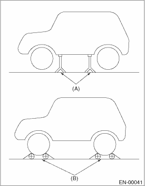
|
(A) |
Rigid racks |
|
(B) |
Free rollers |
1. After clearing the memory, check for any remaining unresolved trouble data.
2. Warm up the engine.
3. Prepare the Subaru Select Monitor kit.
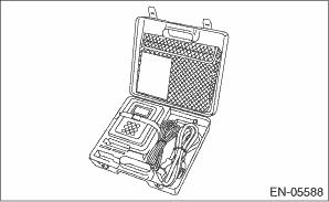
4. Prepare the personal computer which has been installed the Subaru Select Monitor.
5. Connect the USB cable between SDI (Subaru Diagnosis Interface) and USB port on the personal computer (dedicated port for the Subaru Select Monitor).
NOTE:
The dedicated port for the Subaru Select Monitor means the USB port which was used to install the Subaru Select Monitor.
6. Connect the diagnosis cable to the SDI.
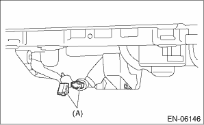
7. Connect the delivery (test) mode connector (A) located under the glove box.
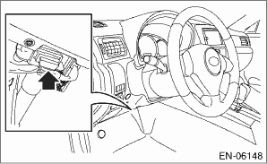
8. Connect the SDI to data link connector located in the lower portion of the instrument panel (on the driver’s side).
CAUTION:
Do not connect any scan tools except Subaru Select Monitor and general scan tool.
9. Start up the PC.
10. Turn the ignition switch to ON (engine OFF), and run the “PC application for Subaru Select Monitor”.
11. On the «Main Menu» display screen, select the {Each System Check}.
12. On the «System Selection Menu» display screen, select the {Engine Control System}.
13. Click the [OK] button after the information of engine type has been displayed.
14. On the «Engine Diagnosis» display screen, select the {Dealer Check Mode Procedure}.
15. When the «Perform Inspection (Dealer Check) Mode» is shown on the screen, click the [Next] button.
16. Perform subsequent procedures as instructed on the display screen.
• If trouble still remains in the memory, the corresponding DTC appears on the display screen.
NOTE:
• For detailed operation procedure, refer to the “PC application help for Subaru Select Monitor”.
• For details concerning DTC, refer to “List of Diagnostic Trouble Code (DTC)”.
• Release the parking brake.
• The speed difference between front and rear wheels may illuminate the ABS warning light, but this does not indicate a malfunction. When engine control diagnosis is finished, perform the ABS memory clearance procedure of the self-diagnosis system.
1. After clearing the memory, check for any remaining unresolved trouble data.
2. Warm up the engine.
3. Connect the delivery (test) mode connector (A) located under the glove box.
4. Connect the general scan tool to data link connector located in the lower portion of the instrument panel (on the driver’s side).
CAUTION:
Do not connect any scan tools except Subaru Select Monitor and general scan tool.
5. Start the engine.
NOTE:
• Make sure the select lever is placed in the “P” position before starting. (AT model)
• Depress the clutch pedal when starting engine. (MT model)
6. Turn the neutral position switch to ON using select lever or shift lever.
7. Depress the brake pedal to turn the brake switch ON. (AT model)
8. Keep the engine speed in 2,500 — 3,000 rpm range for 40 seconds.
9. Place the select lever or shift lever in “D” position (AT model) or “1st gear” (MT model) and drive the vehicle at 5 to 10 km/h (3 to 6 MPH).
NOTE:
• For AWD model, release the parking brake.
• The speed difference between front and rear wheels may illuminate the ABS warning light, but this indicates no malfunctions. When engine control diagnosis is finished, perform the ABS memory clearance procedure of self-diagnosis system.
10. Using the general scan tool, check DTC and record the result(s).
NOTE:
• For detailed operation procedures, refer to the general scan tool operation manual.
• For details concerning DTC, refer to “List of Diagnostic Trouble Code (DTC)”.