1. HOW TO USE GENERAL SCAN TOOL
1. Prepare a scan tool (general scan tool) required by SAE J1978.
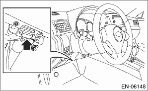
2. Connect the general scan tool to data link connector located in the lower portion of the instrument panel (on the driver’s side).
3. Using the general scan tool, call up DTC and freeze frame data.
General scan tool functions consist of:
(1) MODE $01: Current powertrain diagnostic data
(2) MODE $02: Powertrain freeze frame data
(3) MODE $03: Emission-related powertrain DTC
(4) MODE $04: Clear/Reset emission-related diagnostic information
(5) MODE $06: Request on-board monitoring test results for intermittently monitored systems
(6) MODE $07: Request on-board monitoring test results for continuously monitored systems
(7) MODE $09: Request vehicle information
Read data according to the repairing procedure. (For detailed operation procedure, refer to the general scan tool instruction manual.)
NOTE:
For details concerning DTC, refer to “List of Diagnostic Trouble Code (DTC)”. 
2. MODE $01 (CURRENT POWERTRAIN DIAGNOSTIC DATA)
Refer to data denoting the current operating condition of analog input/output, digital input/output or the powertrain system.
A list of the support data and PID (Parameter Identification) codes are shown in the following table.
|
PID |
Data |
Unit of measure |
|
$01 |
Number of emission-related powertrain DTC, and malfunction indicator light status and diagnosis support information |
— |
|
$03 |
Fuel system control status |
— |
|
$04 |
Calculated engine load value |
% |
|
$05 |
Engine coolant temperature |
°C |
|
$06 |
Short term fuel trim |
% |
|
$07 |
Long term fuel trim |
% |
|
$0B |
Intake manifold absolute pressure |
kPa |
|
$0C |
Engine speed |
rpm |
|
$0D |
Vehicle speed |
km/h, MPH |
|
$0E |
Ignition timing advance |
° |
|
$0F |
Intake air temperature |
°C and °F |
|
$10 |
Air flow rate from mass air flow sensor |
g/sec |
|
$11 |
Throttle valve absolute opening angle |
% |
|
$13 |
Check whether oxygen sensor is installed. |
— |
|
$15 |
Oxygen sensor output voltage and short term fuel trim associated with oxygen sensor (Bank 1 Sensor 2) |
V and % |
|
$1C |
Supporting OBD system |
— |
|
$1F |
Elapsed time after starting the engine |
sec |
|
$21 |
Driving distance after the malfunction indicator light illuminates |
km |
|
$24 |
A/F value and A/F sensor output voltage (Bank 1 Sensor 1) |
— and V |
|
$2C |
Target EGR |
% |
|
$2D |
EGR deviation |
% |
|
$2E |
Evaporative purge |
% |
|
$2F |
Fuel level |
% |
|
$30 |
Number of warm ups after DTC clear |
— |
|
$31 |
Driving distance after DTC clear |
km |
|
$33 |
Atmospheric pressure |
mmHg |
|
$41 |
Diagnostic monitor of each drive cycle |
— |
|
$42 |
ECM power voltage |
V |
|
$43 |
Absolute load |
% |
|
$44 |
A/F target lambda |
— |
|
$45 |
Relative throttle opening angle |
% |
|
$46 |
Ambient temperature |
°C |
|
$47 |
Absolute throttle opening angle 2 |
% |
|
$49 |
Absolute accelerator opening angle 1 |
% |
|
$4A |
Absolute accelerator opening angle 2 |
% |
|
$4C |
Target throttle opening angle |
% |
|
$4D |
Engine operating time while malfunction indicator lit |
min |
|
$4E |
Elapsed time after DTC clear |
min |
|
$51 |
Fuel used |
— |
|
$5A |
Relative accelerator opening angle |
% |
NOTE:
Refer to general scan tool manufacturer’s operation manual to access current powertrain diagnostic data (MODE $01).
3. MODE $02 (POWERTRAIN FREEZE FRAME DATA)
Refer to data denoting the operating condition when trouble is detected by on-board diagnosis system.
A list of the support data and PID (Parameter Identification) codes are shown in the following table.
|
PID |
Data |
Unit of measure |
|
$02 |
DTC that caused the freeze frame data storage required by CARB. |
— |
|
$03 |
Fuel system control status |
— |
|
$04 |
Calculated engine load value |
% |
|
$05 |
Engine coolant temperature |
°C |
|
$06 |
Short term fuel trim (Bank 1 Sensor 1) |
% |
|
$07 |
Long term fuel trim (Bank 1 Sensor 1) |
% |
|
$0B |
Intake manifold absolute pressure |
kPa |
|
$0C |
Engine speed |
rpm |
|
$0D |
Vehicle speed |
km/h, MPH |
|
$0E |
Ignition timing advance |
° |
|
$0F |
Intake air temperature |
°C and °F |
|
$10 |
Air flow rate from mass air flow sensor |
g/sec |
|
$11 |
Throttle valve absolute opening angle |
% |
|
$13 |
Check whether oxygen sensor is installed. |
— |
|
$15 |
Oxygen sensor output voltage and short term fuel trim associated with oxygen sensor (Bank 1 Sensor 2) |
V and % |
|
$1C |
Supporting OBD system |
— |
|
$1F |
Elapsed time after starting the engine |
sec |
|
$2C |
Target EGR |
% |
|
$2D |
EGR deviation |
% |
|
$2E |
Evaporative purge |
% |
|
$2F |
Fuel level |
% |
|
$33 |
Atmospheric pressure |
mmHg |
|
$42 |
ECM power voltage |
V |
|
$43 |
Absolute load |
% |
|
$44 |
A/F target lambda |
— |
|
$45 |
Relative throttle opening angle |
% |
|
$46 |
Ambient temperature |
°C |
|
$47 |
Absolute throttle opening angle 2 |
% |
|
$49 |
Absolute accelerator opening angle 1 |
% |
|
$4A |
Absolute accelerator opening angle 2 |
% |
|
$4C |
Target throttle opening angle |
% |
NOTE:
Refer to general scan tool manufacturer’s instruction manual to access freeze frame data (MODE $02).
4. MODE $03 (EMISSION RELATED POWERTRAIN DTC)
Refer to “Read Diagnostic Trouble Code (DTC)” for information about data denoting emission-related powertrain DTC.
5. MODE $04 (CLEAR/RESET EMISSION RELATED DIAGNOSTIC INFORMATION)
Refer to the mode used to clear or reset emission-related diagnostic information (general scan tool trouble diagnostic information).
NOTE:
Refer to general scan tool manufacturer’s operation manual to clear the emission-related diagnostic information (MODE $04).
Refer to test value of troubleshooting and data of test limit indicated on the support data bit sequence table. A list of the support data is shown in the following table.
|
OBDMID |
TID |
SID |
Diagnostic item |
|
$01 |
$05 |
$10 |
A/F sensor response abnormal (Bank 1 Sensor 1) |
|
$06 |
$10 | ||
|
$81 |
$0C |
A/F sensor continuity abnormal (Bank 1 Sensor 1) | |
|
$82 |
$0E | ||
|
$83 |
$14 | ||
|
$84 |
$0B |
A/F sensor range abnormal (Bank 1 Sensor 1) | |
|
$85 |
$0B | ||
|
$A7 |
$0C | ||
|
$A8 |
$0C | ||
|
$A9 |
$0B | ||
|
$02 |
$05 |
$10 |
Oxygen sensor response abnormal (Bank 1 Sensor 2) |
|
$07 |
$0B |
Oxygen sensor voltage failure (Bank 1 Sensor 2) | |
|
$08 |
$0B | ||
|
$21 |
$89 |
$20 |
Catalyst deterioration diagnosis (Bank 1) |
|
$31 |
$8A |
$FD |
Exhaust gas recirculation control circuit range/performance |
|
$41 |
$99 |
$10 |
A/F sensor heater abnormal (Bank 1 Sensor 1) |
|
$9A |
$10 | ||
|
$9B |
$10 |
A/F sensor heater characteristics abnormal (Bank 1 Sensor 1) | |
|
$AB |
$10 |
A/F sensor heater abnormal (Bank 1 Sensor 1) | |
|
$42 |
$99 |
$0E |
Oxygen sensor heater abnormal (Bank 1 Sensor 2) |
|
$9A |
$0E |
Refer to the data of DTC (pending code) for troubleshooting result about emission in the first time.
Refer to the data of vehicle specification (V.I.N., calibration ID, etc.).