1.CHECK BATTERY.
Check the battery voltage.
|
Is the voltage 12 V or more?
|
|
Charge or replace the battery.
|
2.CHECK OPERATION OF STARTER MOTOR.
|
Does the starter motor operate?
|
|
|
|
|
Is DTC displayed? 
|
Check the appropriate DTC using the List of Diagnostic Trouble Code (DTC).
|
The circuit has returned to a normal condition at this time. Reproduce the fault condition, and reperform the check.
NOTE:
In this case, there may be a temporary connector contact failure.
|
4.CHECK PUSH BUTTON IGNITION SWITCH.
Press the push button ignition switch twice with the ignition OFF (ACC OFF).
NOTE:
• Release the brake pedal. (AT model)
• Release the clutch pedal. (MT model)
|
Does the ignition turn to ON?
|
|
Check the push button start system.
|
5.CHECK PUSH BUTTON IGNITION SWITCH.
1) Depress the brake pedal (AT model) or clutch pedal (MT model).
NOTE:
For AT model, position the select lever in “P” range.
2) Check the push button ignition switch indicator.
|
Does the indicator turn to green?
|
|
Check the brake signal circuit. (AT model)
Check the following item and repair or replace if necessary. (MT model)
• Blown-out of fuse (F/B No. 21)
• Open or ground short circuit of harness between battery and clutch start switch
• Open circuit or short circuit to ground in harness between clutch start switch connector and power supply CM
• Poor contact of clutch start switch
|
6.CHECK START SWITCH SIGNAL.
1) Read the waveform of start switch signal using Subaru Select Monitor.
NOTE:
For detailed operation procedures, refer to “READ CURRENT DATA FOR ENGINE”.
2) Press the push button ignition switch once with brake pedal depressed.
|
Does waveforms of the start switch signal occur?
|
|
|
7.CHECK HARNESS BETWEEN ECM AND POWER SUPPLY CM.
1) Turn the ignition to OFF.
2) Disconnect the connectors from ECM and power supply CM.
3) Measure the resistance of harness between ECM and power supply CM.
Connector & terminal
(B136) No. 32 — (B420) No. 39:
|
Is the resistance less than 1 Ω?
|
|
Repair the open circuit of harness between ECM and power supply CM.
|
8.CHECK HARNESS BETWEEN ECM AND POWER SUPPLY CM.
Measure the resistance between ECM and chassis ground.
Connector & terminal
(B136) No. 32 — Chassis ground:
|
Is the resistance 1 MΩ or more?
|
|
Repair the short circuit to ground in harness between ECM and power supply CM.
|
9.CHECK START SWITCH SIGNAL.
1) Connect the connector to ECM and power supply CM.
2) Read the waveform of start switch signal using an oscilloscope.
3) Press the push button ignition switch once with the brake pedal (AT model) or clutch pedal (MT model) depressed.
Connector & terminal
(B136) No. 32 (+) — Chassis ground (−):
|
Does waveforms of the start switch signal occur?
|
Repair the poor contact of the ECM connector.
|
Repair the poor contact of power supply CM connector.
|
10.CHECK INPUT SIGNAL FOR STARTER MOTOR.
1) Turn the ignition to OFF.
2) Disconnect the connector from starter motor.
3) Set the select lever in “P” range or “N” range (AT model), or the shift lever in neutral (MT model).
4) Press the push button ignition switch once with the brake pedal (AT model) or clutch pedal (MT model) depressed.
5) Measure the voltage between the starter motor connector and the engine ground.
Connector & terminal
(B14) No. 1 (+) — Engine ground (−):
|
Is the voltage 10 V or more?
|
Check the starter motor.
|
|
11.CHECK IG RELAY 1 (PUSH BUTTON START) POWER SUPPLY.
1) Remove the IG relay 1 (push button start).
2) Turn the ignition to ON.
3) Measure the voltage between the IG relay 1 (push button start) connector and chassis ground.
Connector & terminal
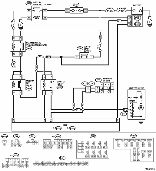
(B425) No. 34 (+) — Chassis ground (−):
(B425) No. 36 (+) — Chassis ground (−):
|
Is the voltage 10 V or more?
|
|
Check the following item and repair or replace if necessary.
• Blown out of fuse
• Open circuit or short circuit to ground in harness between IG relay 1 (push button start) connector and power supply CM
• Open circuit or short circuit to ground in harness between IG relay 1 (push button start) connector and battery
|
12.CHECK HARNESS BETWEEN IG RELAY 1 (PUSH BUTTON START) CONNECTOR AND CHASSIS GROUND.
1) Turn the ignition to OFF.
2) Measure the resistance of harness between the IG relay 1 (push button start) connector and chassis ground.
Connector & terminal
(B425) No. 35 — Chassis ground:
|
Is the resistance less than 5 Ω?
|
|
Repair the open circuit in harness between the IG relay 1 (push button start) connector and chassis ground.
|
13.CHECK IG RELAY 1 (PUSH BUTTON START).
1) Connect the battery to IG relay 1 (push button start) terminals No. 34 and No. 35.
2) Measure the resistance between IG relay 1 (push button start) terminals.
|
Is the resistance less than 1 Ω?
|
|
Replace the IG relay 1 (push button start).
|
14.CHECK STARTER RELAY (PUSH BUTTON START) POWER SUPPLY.
1) Install the IG relay 1 (push button start).
2) Remove the starter relay (push button start).
3) Turn the ignition to ON.
4) Measure the voltage between starter relay (push button start) connector and chassis ground.
Connector & terminal
(B425) No. 22 (+) — Chassis ground (−):
(B425) No. 24 (+) — Chassis ground (−):
|
Is the voltage 10 V or more?
|
|
Check the following item and repair or replace if necessary.
• Blown-out of fuse (F/B No. 26)
• Open circuit or short circuit to ground in harness between starter relay (push button start) connector and IG relay 1 (push button start) connector
• Open circuit or short circuit to ground in harness between starter relay (push button start) connector and battery
|
15.CHECK HARNESS BETWEEN STARTER RELAY (PUSH BUTTON START) CONNECTOR AND CHASSIS GROUND.
1) Turn the ignition to OFF.
2) Measure the resistance of harness between starter relay (push button start) connector and chassis ground.
Connector & terminal
(B425) No. 23 — Chassis ground:
|
Is the resistance less than 5 Ω?
|
|
Repair the open circuit in harness between starter relay (push button start) connector and chassis ground.
|
16.CHECK STARTER RELAY (PUSH BUTTON START).
1) Connect the battery to starter relay (push button start) terminals No. 22 and No. 23.
2) Measure the resistance between starter relay (push button start) terminals.
|
Is the resistance less than 1 Ω?
|
|
Replace the starter relay (push button start).
|
17.CHECK HARNESS BETWEEN STARTER RELAY (PUSH BUTTON START) CONNECTOR AND STARTER CUT RELAY CONNECTOR.
1) Remove the starter cut relay.
2) Measure the resistance of harness between starter relay (push button start) connector and starter cut relay connector.
Connector & terminal
(B425) No. 25 — (B425) No. 1:
(B425) No. 25 — (B425) No. 5:
|
Is the resistance less than 1 Ω?
|
|
Repair the open circuit in harness between starter relay (push button start) connector and starter cut relay connector.
|
18.CHECK HARNESS BETWEEN ECM AND STARTER CUT RELAY CONNECTOR.
1) Disconnect the connectors from the ECM.
2) Measure the resistance between starter cut relay and chassis ground.
Connector & terminal
(B425) No. 3 — Chassis ground:
|
Is the resistance 1 MΩ or more?
|
|
Repair the short circuit to ground in harness between ECM and starter cut relay connector.
|
19.CHECK STARTER CUT RELAY.
Measure the resistance between starter cut relay terminals.
|
Is the resistance less than 1 Ω?
|
|
Replace the starter cut relay.
|
20.CHECK HARNESS BETWEEN STARTER CUT RELAY CONNECTOR AND STARTER RELAY CONNECTOR.
1) Remove the starter relay.
2) Measure the resistance of harness between starter cut relay connector and starter relay connector.
Connector & terminal
(B425) No. 2 — (B225) No. 9:
|
Is the resistance less than 1 Ω?
|
|
Repair the open circuit in harness between starter cut relay connector and starter relay connector.
|
21.CHECK HARNESS BETWEEN ECM AND STARTER RELAY CONNECTOR.
Measure the resistance of harness between ECM and starter relay connector.
Connector & terminal
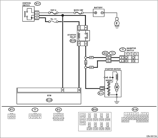
(B136) No. 20 — (B225) No. 12:
|
Is the resistance less than 1 Ω?
|
|
Repair the open circuit of harness between ECM and starter relay connector.
|
22.CHECK STARTER RELAY.
1) Connect the battery to starter relay terminals No. 11 and No. 12.
2) Measure the resistance between starter relay terminals.
|
Is the resistance less than 1 Ω?
|
|
Replace the starter relay.
|
23.CHECK TRANSMISSION TYPE.
|
Is the transmission type AT?
|
|
|
24.CHECK HARNESS BETWEEN STARTER RELAY CONNECTOR AND CLUTCH START SWITCH CONNECTOR.
Measure the resistance of harness between starter relay connector and clutch start switch connector.
Connector & terminal
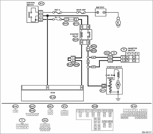
(B225) No. 11 — (B106) No. 2:
|
Is the resistance less than 1 Ω?
|
|
Repair the open circuit of harness between starter relay connector and clutch start switch connector.
|
25.CHECK HARNESS BETWEEN STARTER RELAY CONNECTOR AND STARTER MOTOR.
Measure the resistance of harness between starter relay connector and starter motor.
Connector & terminal
(B225) No. 10 — (B14) No. 1:
|
Is the resistance less than 1 Ω?
|
Check the ECM power supply and ground line.
|
Repair the open circuit of the harness between starter relay connector and starter motor.
|
26.CHECK HARNESS BETWEEN STARTER CUT RELAY CONNECTOR AND STARTER RELAY CONNECTOR.
Measure the resistance of harness between starter cut relay connector and starter relay connector.
Connector & terminal
(B425) No. 2 — (B225) No. 11:
|
Is the resistance less than 1 Ω?
|
|
Repair the open circuit in harness between starter cut relay connector and starter relay connector.
|
27.CHECK HARNESS BETWEEN STARTER RELAY AND INHIBITOR SWITCH CONNECTOR.
1) Disconnect the connector from inhibitor switch.
2) Measure the resistance of harness between starter relay and inhibitor switch connector.
Connector & terminal
(B225) No. 10 — (T7) No. 6:
|
Is the resistance less than 1 Ω?
|
|
Repair the harness and connector.
NOTE:
In this case, repair the following item:
• Open circuit in harness between starter relay and inhibitor switch connector
• Poor contact of coupling connector
|
28.CHECK INHIBITOR SWITCH.
1) Place the select lever in “P” range or “N” range.
2) Measure the resistance between inhibitor switch terminals.
|
Is the resistance less than 1 Ω?
|
|
Replace the inhibitor switch.
|
29.CHECK NEUTRAL POSITION SWITCH SIGNAL.
1) Connect all the relays and connectors properly.
2) Read the neutral position switch signal using Subaru Select Monitor.
NOTE:
For detailed operation procedures, refer to “READ CURRENT DATA FOR ENGINE”.
3) Turn the ignition to ON.
4) Place the select lever in “P” range or “N” range.
|
|
Check the ECM power supply and ground line.
|
Repair the harness and connector.
NOTE:
In this case, repair the following item:
• Open circuit in harness between inhibitor switch connector and starter motor
• Poor contact of coupling connector
|