1. MODEL WITHOUT PUSH BUTTON START
DTC DETECTING CONDITION:
Immediately at fault recognition
TROUBLE SYMPTOM:
Failure of engine to start
CAUTION:
After repairing or replacing the defective part, perform the Clear Memory Mode  and Inspection Mode .
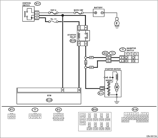
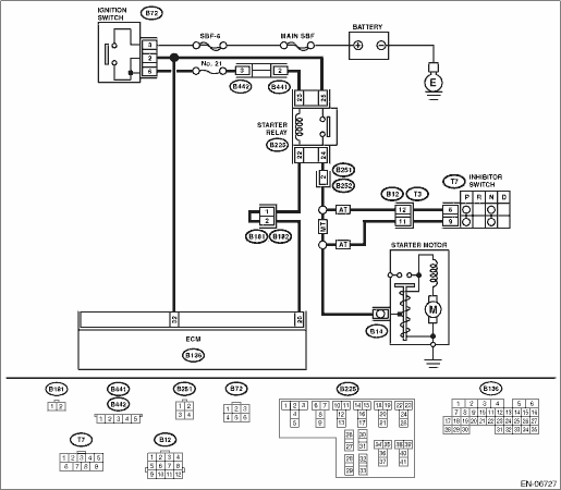
WIRING DIAGRAM:
• LHD model

• RHD model
| STEP | CHECK | YES | NO |
|
Is any other DTC displayed? |
Check the appropriate DTC using the “List of Diagnostic Trouble Code (DTC)”. |
|
|
|
Is the voltage 10 V or more? |
Repair the short circuit to power in the harness between ECM and ignition switch. |
Repair the poor contact of the ECM connector. |
2. MODEL WITH PUSH BUTTON START
DTC DETECTING CONDITION:
Immediately at fault recognition
TROUBLE SYMPTOM:
Failure of engine to start
CAUTION:
After repairing or replacing the defective part, perform the Clear Memory Mode and Inspection Mode .
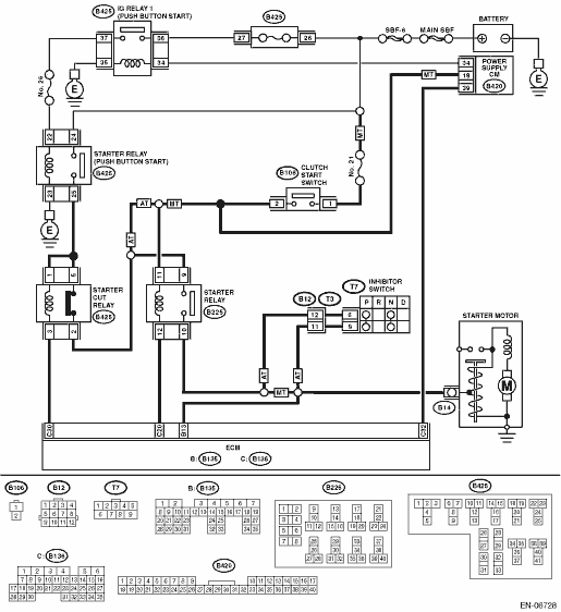
WIRING DIAGRAM:
| STEP | CHECK | YES | NO |
|
Does it operate smoothly without catch? |
|
Replace the push button ignition switch. |
|
|
Is the same DTC as current diagnosis output? |
|
The circuit has returned to a normal condition at this time. Reproduce the fault condition, and reperform the check. |
|
|
Is the voltage 10 V or more? |
Repair the short circuit to power supply in harness between ECM and power supply CM. |
Repair the poor contact of the ECM connector. |