1. KEYLESS ACCESS LOCK/UNLOCK CANNOT BE PERFORMED FROM ANY OF THE DOORS
Possible parts that have problems
• Access key or access key battery
• Key interlocked switch circuit within the driver’s door lock
• Door switch circuit within each door
CAUTION:
• Check that there are no other registered access keys inside the vehicle.
• Inspect LAN system according to the basic diagnostic procedure, and make sure that there is no fault.
• Check that the keyless access function is not stopped.
• When the access key or collation CM is replaced, registration of the immobilizer is required. For procedures, refer to the “PC application help for Subaru Select Monitor”.
| STEP | CHECK | YES | NO |
|
Does it operate properly? |
|
Perform the diagnosis for the door lock control system. |
|
|
Is it only LOCK which does not operate? |
|
|
|
|
Does it lock/unlock normally? |
|
Check the access key and outside access antenna. |
|
|
Is there any access key which can not lock/unlock? |
Replace the access key that does not operate. |
|
|
|
Does each door data change from ON/OFF? |
Replace the collation CM. |
Check the door switch circuit. |

2. ALL KEYLESS ACCESS FUNCTIONS DO NOT OPERATE
CAUTION:
• Inspect LAN system according to the basic diagnostic procedure, and make sure that there is no fault.
• Check that the keyless access function is not stopped.
• When the access key or the collation CM is replaced, refer to “PC application help for Subaru Select Monitor” for procedures regarding the required immobilizer registration.
| STEP | CHECK | YES | NO |
|
Is the keyless access system in a stop status? |
Release the keyless access function stop status. |
|
|
|
Is the voltage 10 V or more? |
|
Repair or replace the open circuit of harness. |
|
|
Is there continuity? |
Replace the collation CM. |
Repair or replace the short circuit of the harness. |
3. CANNOT LOCK WITH KEYLESS ACCESS FROM THE DRIVER’S DOOR
CAUTION:
• Check that there are no other registered access keys inside the vehicle.
• Inspect LAN system according to the basic diagnostic procedure, and make sure that there is no fault.
• Check that the keyless access function is not stopped.
• Check that the cut connector for external buzzer beep does not connected. (Model for China)
• When the access key or the collation CM is replaced, refer to “PC application help for Subaru Select Monitor” for procedures regarding the required immobilizer registration.
| STEP | CHECK | YES | NO |
|
Does it lock/unlock normally? |
|
Check the door lock circuit. |
|
|
Does the data change from ON/OFF? |
Replace the collation CM. |
Check the door lock switch circuit. |
4. CANNOT LOCK/UNLOCK WITH KEYLESS ACCESS FROM THE DRIVER’S DOOR
CAUTION:
• Check that there are no other registered access keys inside the vehicle.
• Inspect LAN system according to the basic diagnostic procedure, and make sure that there is no fault.
• Check that the keyless access function is not stopped.
• When the access key or the collation CM is replaced, refer to the “PC application help for Subaru Select Monitor” for procedures regarding the required immobilizer registration.
| STEP | CHECK | YES | NO |
|
Does it lock/unlock normally? |
|
Check the door lock circuit. |
|
|
Is the fuse OK? |
|
Replace the fuse. |
|
|
Is the voltage 10 V or more? |
|
Repair or replace the open circuit of harness. |
|
|
Is there continuity? |
|
Repair or replace the open circuit of harness. |
|
|
Is there continuity? |
|
Repair or replace the open circuit of harness. |
|
|
Is there continuity? |
|
Repair or replace the open circuit of harness. |
|
|
Is it operating normally? |
Replace the oscillator. |
|
|
|
Is it operating normally? |
Replace the door lock/unlock button. |
|
|
|
1) Using the Subaru Select Monitor, from the “Keyless access system check of collation CM”, select the «System check». 2) From the “System check”, select the «Driver’s exterior transmitter + interior tuner». 3) While in possession of the access key, stand 1 m or more away from the driver’s side door, then move approximately 0.8 m or closer. |
Did the buzzer sound? |
|
Replace the collation CM. |
|
1) Using the Subaru Select Monitor, from the “Keyless access system check of collation CM”, select the «System check». 2) From the “System check”, select the «Driver’s exterior transmitter + interior tuner». 3) Using a tester, measure the output (waveform) between the collation CM terminals. Connector & terminal (B421) No. 33 — No. 34: |
When the system check was performed, did a change occur from waveform output to no waveform output? |
|
Replace the collation CM. |
|
Does the keyless access system operate normally? |
Replace the access antenna. |
Replace the collation CM. |
5. CANNOT UNLOCK WITH KEYLESS ACCESS FROM THE DRIVER’S DOOR
CAUTION:
• Check that there are no other registered access keys inside the vehicle.
• Inspect LAN system according to the basic diagnostic procedure, and make sure that there is no fault.
• Check that the keyless access function is not stopped.
• When the access key or the collation CM is replaced, refer to “PC application help for Subaru Select Monitor” for procedures regarding the required immobilizer registration.
| STEP | CHECK | YES | NO |
|
Does it lock/unlock normally? |
|
Check the door lock circuit. |
|
|
Does the data change from ON/OFF? |
Replace the collation CM. |
Check the door lock switch circuit. |
6. CANNOT UNLOCK WITH KEYLESS ACCESS FROM THE PASSENGER’S DOOR
CAUTION:
• Check that there are no other registered access keys inside the vehicle.
• Inspect LAN system according to the basic diagnostic procedure, and make sure that there is no fault.
• Check that the keyless access function is not stopped.
• When the access key or the collation CM is replaced, refer to “PC application help for Subaru Select Monitor” for procedures regarding the required immobilizer registration.
| STEP | CHECK | YES | NO |
|
Does it lock/unlock normally? |
|
Check the door lock circuit. |
|
|
Does the data change from ON/OFF? |
Replace the collation CM. |
Check the door lock switch circuit. |
7. CANNOT LOCK/UNLOCK WITH KEYLESS ACCESS FROM THE PASSENGER’S DOOR
CAUTION:
• Check that there are no other registered access keys inside the vehicle.
• Inspect LAN system according to the basic diagnostic procedure, and make sure that there is no fault.
• Check that the keyless access function is not stopped.
• When the access key or the collation CM is replaced, refer to the “PC application help for Subaru Select Monitor” for procedures regarding the required immobilizer registration.
| STEP | CHECK | YES | NO |
|
Does it lock/unlock normally? |
|
Check the door lock circuit. |
|
|
Is the fuse OK? |
|
Replace the fuse. |
|
|
Is the voltage 10 V or more? |
|
Repair or replace the open circuit of harness. |
|
|
Is there continuity? |
|
Repair or replace the open circuit of harness. |
|
|
Is there continuity? |
|
Repair or replace the open circuit of harness. |
|
|
Is there continuity? |
|
Repair or replace the open circuit of harness. |
|
|
Is it operating normally? |
Replace the oscillator. |
|
|
|
Is it operating normally? |
Replace the door lock/unlock button. |
|
|
|
1) Using the Subaru Select Monitor, from the “Keyless access system check of collation CM”, select the «System check». 2) From the “System check”, select the «Passenger’s exterior transmitter + interior tuner». 3) While in possession of the access key, stand 1 m or more away from the passenger’s side door, then move approximately 0.8 m or closer. |
Did the external buzzer sound? |
|
Replace the collation CM. |
|
1) Using the Subaru Select Monitor, from the “Keyless access system check of collation CM”, select the «System check». 2) From the “System check”, select the «Passenger’s exterior transmitter + interior tuner». 3) Using a tester, measure the output (waveform) between the collation CM terminals. Connector & terminal (B421) No. 35 — No. 36: |
When the system check was performed, did a change occur from waveform output to no waveform output? |
|
Replace the collation CM. |
|
Does the keyless access system operate normally? |
Replace the access antenna. |
Replace the collation CM. |
8. CANNOT LOCK WITH KEYLESS ACCESS FROM THE PASSENGER’S DOOR
CAUTION:
• Check that there are no other registered access keys inside the vehicle.
• Inspect LAN system according to the basic diagnostic procedure, and make sure that there is no fault.
• Check that the keyless access function is not stopped.
• When the access key or the collation CM is replaced, refer to “PC application help for Subaru Select Monitor” for procedures regarding the required immobilizer registration.
| STEP | CHECK | YES | NO |
|
Does it lock/unlock normally? |
|
Check the door lock circuit. |
|
|
Does the data change from ON/OFF? |
Replace the collation CM. |
Check the door lock switch circuit. |
9. THE KEYLESS ACCESS PASSENGER ROOM BUZZER DOES NOT SOUND
CAUTION:
• Inspect LAN system according to the basic diagnostic procedure, and make sure that there is no fault.
• Check that the keyless access function is not stopped.
• When the access key or the collation CM is replaced, refer to the “PC application help for Subaru Select Monitor” for procedures regarding the required immobilizer registration.
| STEP | CHECK | YES | NO |
|
Is the self-diagnosis OK? |
Replace the collation CM. |
Replace the combination meter. |
10. INTERNAL COLLATION DOES NOT FUNCTION
CAUTION:
When the access key or collation CM is replaced, registration of the immobilizer is required. For procedures, refer to the “PC application help for Subaru Select Monitor”.
| STEP | CHECK | YES | NO |
|
Is a pulse output? |
|
Replace the collation CM. |
|
|
Is a pulse output? |
|
Replace the collation CM. |
|
|
Is a pulse output? |
|
Replace the collation CM. |
|
|
1) Disconnect the front passenger room antenna connector and the collation CM connector. 2) Using a tester, check continuity between the front passenger room antenna connector and the collation CM connector. Connector & terminal (i25) No. 1 — (B421) No. 11: (i25) No. 3 — (B421) No. 12: |
Is there continuity? |
|
Repair or replace the open circuit of harness. |
|
1) Disconnect the center passenger room antenna connector and the collation CM connector. 2) Using a tester, check continuity between the center passenger room antenna connector and the collation CM connector. Connector & terminal (R298) No. 1 — (B421) No. 13: (R298) No. 3 — (B421) No. 14: |
Is there continuity? |
|
Repair or replace the open circuit of harness. |
|
1) Disconnect the rear passenger room antenna connector and the collation CM connector. 2) Using a tester, check continuity between the rear passenger room antenna connector and the collation CM connector. Connector & terminal (R299) No. 1 — (B421) No. 15: (R299) No. 3 — (B421) No. 16: |
Is there continuity? |
|
Repair or replace the open circuit of harness. |
|
Does it operate properly? |
Replace the front passenger room antenna. |
|
|
|
Does it operate properly? |
Replace the center passenger room antenna. |
|
|
|
Does it operate properly? |
Replace the rear passenger room antenna. |
|
|
|
Does it operate properly? |
Replace the receiver. |
|
|
|
Is there continuity? |
|
Repair or replace the open circuit of harness. |
|
|
1) Using the Subaru Select Monitor, from the “Keyless access system check of collation CM”, select the «System check». 2) From the “System check”, select the «Front interior transmitter + interior tuner». 3) Hold the access key 1 m or more away from the audio panel, then come closer to within 0.8 m. |
Does the buzzer sound? |
|
Replace the collation CM. |
|
1) Using the Subaru Select Monitor, from the “Keyless access system check of collation CM”, select the «System check». 2) From the “System check”, select the «Rear interior transmitter + interior tuner». 3) Hold the access key 1 m or more away from the center of the second row seats, then come closer to within 0.8 m. |
Does the buzzer sound? |
|
Replace the collation CM. |
|
1) Using the Subaru Select Monitor, from the “Keyless access system check of collation CM”, select the «System check». 2) From the system check, select «Trunk internal transmitter + interior tuner», or «Rear gate internal transmitter + interior tuner». 3) Hold the access key 1 m or more away from the back of the rear seat, then come closer to within 0.8 m. |
Does the buzzer sound? |
System is normal. |
Replace the collation CM. |
11. CAN NOT LOCK WHEN USING THE REAR LOCK BUTTON
CAUTION:
• Check that there are no other registered access keys inside the vehicle.
• Inspect LAN system or keyless access system according to the basic diagnostic procedure, and make sure that DTC is not input.
• When the access key, body integrated unit or the collation CM is replaced, refer to “PC application help for Subaru Select Monitor” for procedures regarding the required immobilizer registration.
| STEP | CHECK | YES | NO |
|
Does the data change between ON/OFF? |
|
|
|
|
Is the resistance less than 10 Ω? |
|
Repair or replace the open circuit of the harness. |
|
|
Is the resistance less than 10 Ω? |
|
Repair or replace the short of harness. |
|
|
Is the resistance less than 10 Ω? |
|
Repair or replace the open circuit of the harness. |
|
|
Did the resistance change from 1 MΩ or more to less than 10 Ω? |
|
Replace the rear lock button. |
|
|
Does the rear gate open with rear gate opener button? |
|
It is possible that temporary poor communication occurs. |
|
|
Is the rear gate lock actuator normal? |
Replace the body integrated unit. |
Replace the rear gate latch assembly. |
12. THE STEERING LOCK IS NOT RELEASED
| STEP | CHECK | YES | NO |
|
The steering lock is released, but the engine is not started. |
|
|
|
|
Is a DTC displayed? |
Perform the diagnosis according to the corresponding procedures of DTC. |
|
|
|
Is a DTC displayed? |
Perform the diagnosis according to the corresponding procedures of DTC. |
|
|
|
1) Using the Subaru Select Monitor, display the current data of the collation CM «Steering lock/unlock request reception status» and «Steering lock/unlock command reception history». 2) Read the data when the push button ignition switch is pressed while in possession of the access key. (Maintain for 10 seconds after switch operation) |
Does the data change from «Not yet received» to «Reception», and from «OFF» to «ON»? |
|
|
|
Is the voltage 10 V or more? |
|
Repair or replace the open circuit of harness. |
|
|
Is the voltage 10 V or more? |
|
Repair or replace the open circuit of harness. |
|
|
Is the voltage 1 V or less right after the ignition ON? |
Replace the steering lock CM. |
Repair or replace the open circuit of harness. |
|
|
Is data displayed as being normal? |
|
|
|
|
Is data displayed as being normal? |
System is normal. |
Replace the collation CM. |
|
|
Is data displayed as being normal? |
System is normal. |
|
|
|
Is data displayed as being normal? |
System is normal. |
|
|
|
1) Replace with a properly functioning or new steering lock CM. Refer to the “PC application help for Subaru Select Monitor”. 2) After registering, the steering lock operates when the ignition is turned to OFF and the driver’s door is opened and closed. 3) Turn the ignition to ON. 4) Operate the steering and check for whether the steering lock is released. |
Is the steering lock released, and does the engine start? |
Replace the steering lock CM. |
Replace the collation CM. |
13. THE STEERING LOCK DOES NOT OPERATE
| STEP | CHECK | YES | NO |
|
Is a DTC displayed? |
Perform the diagnosis according to the corresponding procedures of DTC. |
|
|
|
Is a DTC displayed? |
Perform the diagnosis according to the corresponding procedures of DTC. |
|
|
|
Does the data change from ON to OFF according to the opening and closing? |
|
Inspect door switch circuit. |
|
|
Is data displayed as being received? |
|
Replace the collation CM. |
|
|
Using a tester, measure the waveform between steering lock CM terminals immediately after the following operations. Perform ignition ON, driver’s side door close, shift lever P range, ignition off, and close → open the driver’s side door. Connector & terminal (B424) No. 3 — No. 2: |
Is the waveform immediately after opening the driver’s side door abnormal? |
Replace the steering lock CM. |
|
|
Is there continuity? |
|
Repair or replace the open circuit of harness. |
|
|
Is there continuity? |
Repair or replace the short circuit of the harness. |
Replace the power supply CM. |
14. THE KEYLESS ACCESS EXTERNAL BUZZER DOES NOT BEEP
| STEP | CHECK | YES | NO |
|
Does the buzzer sound? |
|
Check the buzzer circuit. |
|
|
Does the buzzer sound in each mode? |
Currently, system is normal. |
Check the buzzer circuit. |
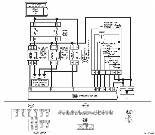
15. POWER WILL NOT TURN ON (BOTH ACCESSORY AND IGNITION)
CAUTION:
When the power supply CM is replaced with a new unit, and the battery ground terminal is connected, it will become ignition ON. Also, if the battery is disconnected, it will resume to a condition with the battery cut off.
WIRING DIAGRAM:

| STEP | CHECK | YES | NO |
|
Is the fuse OK? |
|
Replace the fuse. |
|
|
Is the voltage 10 V or more? |
|
Check the DC power supply circuit. |
|
|
Are the connectors and terminals normal? |
|
Repair the connector, or replace harness. |
|
|
Is the voltage between 8 V and 16 V? |
|
Repair or replace the open circuit of harness. |
|
|
Is there continuity? |
|
Replace the collation CM. |
|
|
Is the key collation error being output? |
|
Perform diagnosis according to the DTC. |
|
|
Does it change from OFF to ON along with the operation? |
|
|
|
|
Is IG relay 1, 2 (Push button start) normal? |
|
Replace the faulty relay. |
|
|
1) Disconnect power supply CM connector, IG relay 1 (push button start), IG relay 2 (push button start) and accessory relay (push button start). 2) Using a tester, check continuity between terminals of power supply CM connector, IG relay 1 (push button start), IG relay 2 (push button start) and accessory relay (push button start). Connector & terminal (B420) No. 35 — (B425) No. 38: (B420) No. 34 — (B425) No. 34: (B420) No. 11 — (B426) No. 4: |
Is there continuity? |
|
Repair or replace the open circuit of harness. |
|
Is there no continuity? |
|
Repair or replace the short circuit of the harness. |
|
|
Is there continuity? |
|
Repair or replace the open circuit of harness. |
|
|
Is there continuity? |
|
Repair or replace the short circuit of the harness. |
|
|
Is there continuity? |
|
Repair or replace the short circuit of the harness. |
|
|
1) Connect all the disconnected connectors. 2) Using a tester, measure the voltage between the power supply CM connector and chassis ground when the ignition is turned to OFF and to ON. Connector & terminal (B420) No. 11 (+) — Chassis ground (−): (B420) No. 34 (+) — Chassis ground (−): (B420) No. 35 (+) — Chassis ground (−): |
Does the voltage change from less than 1 V to +B−2 V or more? |
|
Replace the power supply CM. |
|
When the button was pressed, did it change to continuity exists? (No continuity when button is released) |
|
Replace the power supply CM. |
|
|
Is there continuity? |
|
Repair or replace the open circuit of harness. |
|
|
Did it change to continuity exists, when the button was pressed? |
Replace the push button ignition switch. |
Repair or replace the open circuit of harness. |
16. POWER WILL NOT TURN ON (ACCESSORY DOES NOT TURN ON, BUT IGNITION TURNS ON)
CAUTION:
When the power supply CM is replaced with a new unit, and the battery ground terminal is connected, it will become ignition ON. Also, if the battery is disconnected, it will resume to a condition with the battery cut off.
WIRING DIAGRAM:
| STEP | CHECK | YES | NO |
|
Is the fuse OK? |
|
Replace the fuse. |
|
|
Are the connectors and terminals normal? |
|
Repair the connector, or replace harness. |
|
|
Is the voltage between 8 V and 16 V? |
|
Repair or replace the open circuit of harness. |
|
|
Is there continuity? |
|
Replace the collation CM. |
|
|
Is the relay OK? |
|
Replace the relay. |
|
|
Is there continuity? |
|
Repair or replace the open circuit of harness. |
|
|
Is there continuity? |
Repair or replace the short circuit of the harness. |
|
|
|
Did the voltage change from 1 V or less to → + B - 2 V or more? |
System is normal. |
Replace the power supply CM. |
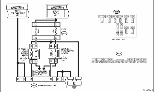
17. POWER WILL NOT TURN ON (ACCESSORY TURNS ON, BUT IGNITION DOES NOT TURN ON)
CAUTION:
When the power supply CM is replaced with a new unit, and the battery ground terminal is connected, it will become ignition ON. Also, if the battery is disconnected, it will resume to a condition with the battery cut off.
WIRING DIAGRAM:
| STEP | CHECK | YES | NO |
|
Is the fuse OK? |
|
Replace the fuse. |
|
|
Are the connectors and terminals normal? |
|
Repair the connector, or replace harness. |
|
|
Is the voltage between 8 V and 16 V? |
|
Repair or replace the open circuit of harness. |
|
|
Is there continuity? |
|
Replace the collation CM. |
|
|
Is the relay OK? |
|
Replace the relay. |
|
|
1) Disconnect the power supply CM connector and the IG relay 1 and 2 (push button start). 2) Using a tester, check continuity between power supply CM connector and IG relay 1 (push button start) or IG relay 2 (push button start). Connector & terminal (B420) No. 35 — (B425) No. 38: (B420) No. 34 — (B425) No. 34: |
Is there continuity? |
|
Repair or replace the open circuit of harness. |
|
Is there continuity? |
Repair or replace the short circuit of the harness. |
|
|
|
1) Connect the power supply CM connector. 2) Using a tester, measure the voltage between the power supply CM connector and chassis ground when the ignition is turned to OFF and to ON. Connector & terminal (B420) No. 34 (+) — Chassis ground (−): (B420) No. 35 (+) — Chassis ground (−): |
Did the voltage change from 1 V or less to → + B - 2 V or more? |
System is normal. |
Replace the power supply CM. |
| STEP | CHECK | YES | NO |
|
Does the engine start? |
System is normal. |
|
|
|
Is DTC detected? |
Perform the diagnosis according to the DTC. |
|
|
|
When the switch is operated, does the <IG-OFF> → <ACC-ON> → <IG-ON> → <IG-OFF> change occur? |
|
Perform the diagnostics according to the symptom for power supply switching system in General Diagnostic Table. |
|
|
1) Place the access key on the driver’s seat. 2) Push the push button ignition switch without depressing the brake pedal or clutch pedal. 3) Using the Subaru Select Monitor, confirm the power supply CM, the current data «STSW monitor» when pressing the push button ignition switch. NOTE: If it is difficult to confirm, press the push button ignition switch for approximately five seconds longer. |
Does the data change from ON → OFF? |
|
AT model, MT model, |
|
Is ON displayed in parking position, and OFF displayed in other positions? |
|
|
|
|
Is ON displayed when brake pedal depressed, and OFF displayed when brake pedal not depressed? |
|
|
|
|
AT model: is ON displayed in parking and neutral position and OFF displayed in other positions? MT model: is ON displayed when clutch pedal depressed and OFF displayed when clutch pedal not displayed? |
|
|
|
|
Is steering lock UNLOCK condition? |
|
Perform the diagnostics according to the symptom for steering lock system in General Diagnostic Table. |
|
|
1) Turn the ignition switch to OFF. 2) Disconnect the connector of ECM. 3) Use a tester to measure the battery voltage in following procedures. (1) Press the push button ignition switch with the brake pedal depressed (MT model: clutch pedal depressed). (Measure within 10 seconds.) (2) Release the push button ignition switch from the condition of step 1. above. Connector & terminal (B420) No. 39 (+) — Chassis ground (−): |
Does the value change from 1 V or less to +B-2 V or more in the step 1. above, and return to 1 V or less in the step 2. above? |
Perform fault diagnosis for the engine system. |
Replace the power supply CM. |
|
Is “Reception” displayed with ignition switch ON, and “Not yet received” displayed in other positions? |
|
|
|
|
Can the engine start? |
There was a malfunction in the ID code box. |
Perform fault diagnosis for the engine system. |
|
|
Does it change from Continuity ⇔ No continuity according to shift lever operation? |
|
Replace the P range switch. |
|
|
Is there continuity? |
Replace the power supply CM. |
Repair or replace the harness. |
|
|
Does it change from Continuity ⇔ No continuity according to brake pedal operation? |
|
Replace the stop light switch. |
|
|
Is there continuity? |
Replace the power supply CM. |
Repair or replace the harness. |
|
|
Is the inhibitor switch working normal? |
|
Replace the inhibitor switch. |
|
|
Is clutch switch OK? |
|
Replace the clutch switch. |
|
|
Is there continuity? |
Replace the power supply CM. |
Repair or replace the harness. |
|
|
Is there continuity? |
Replace the power supply CM. |
Repair or replace the harness. |
|
|
Can the engine start? |
There was a malfunction in the collation CM. |
Replace the ID code box. |