
NOTE:
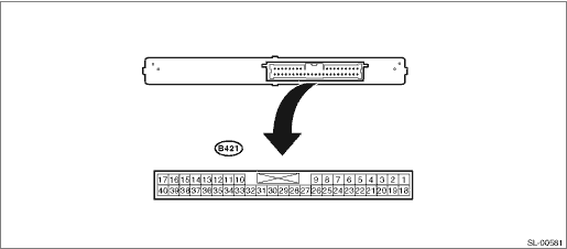
Disconnect the control module connector before checking the following items.
|
Terminal No. |
Standard |
Measuring condition |
Item |
|
17 (GND) ←→ Chassis ground |
Continuity exists |
Always |
Continuity |
|
1 (+B) ←→ 17 (GND) |
10 — 14 V |
Always |
Voltage |
|
18 (IG) ←→ 17 (GND) |
0 V→ 10 — 14 V |
Ignition OFF → Ignition ON |
Voltage |
|
19 (ACC) ←→ 17 (GND) |
0 V→ 10 — 14 V |
Ignition OFF → ACC ON |
Voltage |
|
27 (MPX1) ←→ 17 (GND) |
Pulse generation |
Ignition ON |
Voltage |
|
28 (MPX2) ←→ 17 (GND) |
Pulse generation |
Ignition ON |
Voltage |
|
3 (TSW1) (+) ←→ 17 (GND) (−) |
Continuity does not exist → Exists |
Driver’s door lock/unlock button OFF → ON |
Continuity |
|
4 (TSW2) (+) ←→ 17 (GND) (−) |
Continuity does not exist → Exists |
Passenger’s door lock/unlock button OFF → ON |
Continuity |
NOTE:
If the measured value is out of standard, it is possible that the vehicle has a fault.
Connect the control module connector before checking the following items.
|
Terminal No. |
Standard |
Measuring condition |
Item |
|
11 (CLG5) ←→ 12 (CG5B) |
Hz output exists → Does not exist |
Driver’s side door open → close or close → open, and after 30 seconds the ignition OFF → Ignition ON |
Hz |
|
13 (CLG6) ←→ 14 (CG6B) |
Hz output exists → Does not exist |
Driver’s side door open → close or close → open, and after 30 seconds the ignition OFF → Ignition ON |
Hz |
|
15 (CLG7) ←→ 16 (CG7B) |
Hz output does not exist → Exists |
Rear gate opener button OFF → ON |
Hz |
|
29 (RCO) ←→ 17 (GND) |
1 V or less → 4.6 — 5.4 V |
With the ignition OFF, and with all doors closed and locked, access key lock and unlock switch OFF → ON |
Voltage |
|
31 (CLG8) ←→ 32 (CG8B) |
Hz output does not exist → Exists |
Rear gate opener button OFF → ON |
Hz |
|
33 (CLG1) ←→ 34 (CG1B) |
Hz output exists → Does not exist |
With the ignition OFF and all doors closed, lock → unlock by the wireless operation from outside the vehicle |
Hz |
|
35 (CLG2) ←→ 36 (CG2B) |
Hz output exists → Does not exist |
With the ignition OFF and all doors closed, lock → unlock by the wireless operation from outside the vehicle |
Hz |
|
37 (ASEL) ←→ 17 (GND) |
1 V or less → 4.6 — 5.4 V |
All doors unlock, rear lock button OFF → ON |
Voltage |
|
38 (RDA) ←→ 17 (GND) |
1 V or less → Approx. 11 V → 1 V or less |
With the ignition OFF and with all doors closed, access key switch OFF → ON |
Voltage |
|
39 (RSSI) ←→ 17 (GND) |
Approx. 11 V → 1 V or less |
With the ignition OFF, and all doors closed and unlocked, access key outside area → Within area |
Voltage |
|
21 (BZR) ←→ 17 (GND) |
Hz output does not exist → Exists |
Door close → door open in a range other than P |
Hz |
|
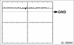
8 (TXCT) ←→ 40 (AGND) |
1 V or less |
When access key is not inside the vehicle |
Voltage |
|
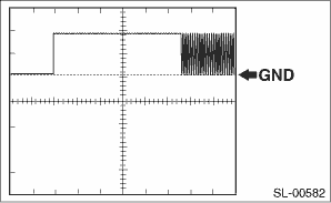
8 (TXCT) ←→ 40 (AGND) |
Waveform 1 |
With the access key near the push button ignition switch, press the push button ignition switch *1 |
Voltage |
|
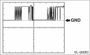
9 (CODE) ←→ 40 (AGND) |
1 V or less |
When access key is not inside the vehicle |
Voltage |
|
9 (CODE) ←→ 40 (AGND) |
Waveform 2 |
With the access key near the push button ignition switch, press the push button ignition switch *1 |
Voltage |
|
30 (VC5) ←→ 40 (AGND) |
1 V or less |
When access key is not inside the vehicle |
Voltage |
|
30 (VC5) ←→ 40 (AGND) |
4.6 — 5.4 V |
Push button ignition switch pressed |
Voltage |
|
40 (AGND) ←→ Chassis ground |
Continuity exists |
Always |
Continuity |
NOTE:
• If the measured value is out of standard, it is possible that the collation CM has a fault.
• *1: Remove the access key battery before checking.
(1) Waveform 1
|
Item |
Content |
|
Measured terminal |
8 (TXCT) ←→ 40 (AGND) |
|
Equipment setting |
2 V/DIV, 20 ms/DIV |
|
Measuring condition |
With the access key near the push button ignition switch, press the push button ignition switch *1 |
NOTE:
*1: Remove the access key battery before checking.
(2) Waveform 2
|
Item |
Content |
|
Measured terminal |
9 (CODE) ←→ 40 (AGND) |
|
Equipment setting |
2 V/DIV, 20 ms/DIV |
|
Measuring condition |
With the access key near the push button ignition switch, press the push button ignition switch *1 |
NOTE:
If the measured value is out of standard, it is possible that the vehicle has a fault.
NOTE:
Disconnect the control module connector before checking the following items.
NOTE:
Connect the control module connector before checking the following items.
|
Terminal No. |
Standard |
Measuring condition |
Item |
|
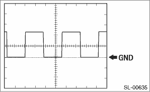
5 (EFII) ←→ 8 (GND) |
0 V |
Ignition OFF |
Voltage |
|
5 (EFII) ←→ 8 (GND) |
Waveform 1 |
Ignition ON |
Voltage |
|
6 (EFIO) ←→ 8 (GND) |
0 V |
Ignition OFF |
Voltage |
|
6 (EFIO) ←→ 8 (GND) |
Waveform 1 |
Ignition ON |
Voltage |
Waveform 1
|
Item |
Content |
|
Measured terminal |
5 (EFII) ←→ 8 (GND) |
|
Equipment setting |
10 V/DIV, 100 ms/DIV |
|
Measuring condition |
Ignition ON |
Refer to the Control Module I/O Signal of the LAN SYSTEM. 
NOTE:
Disconnect the control module connector before checking the following items.
|
Terminal No. |
Standard |
Measuring condition |
Item |
|
6 (GND2) ←→ Chassis ground |
Continuity exists |
Always |
Continuity |
|
40 (GND) ←→ Chassis ground |
Continuity exists |
Always |
Continuity |
|
12 (AM2) ←→ 6 (GND2) |
9.5 — 16 V |
Always |
Voltage |
|
33 (AM1) ←→ 6 (GND2) |
9.5 — 16 V |
Always |
Voltage |
|
14 (SSW1) ←→ Chassis ground |
Continuity exists → Does not exist |
Push button ignition switch pressed → released |
Continuity |
|
37 (SSW2) ←→ Chassis ground |
Continuity exists → Does not exist |
Push button ignition switch pressed → released |
Continuity |
|
1 (STP) ←→ Chassis ground |
2 V or more → less than 1 V |
Brake pedal pressed → Released |
Voltage |
|
30 (LIN1) ←→ Chassis ground |
Continuity does not exist |
Always |
Continuity |
NOTE:
If the measured value is out of standard, it is possible that the vehicle has a fault.
NOTE:
Connect the connector before checking the following items.
|
Terminal No. |
Standard |
Measuring condition |
Item |
|
11 (ACCD) ←→ 6 (GND2) |
1 V or less → {(AM1 or AM2) -2 V} or more |
Ignition OFF → ACC ON |
Voltage |
|
34 (IG1D) ←→ 6 (GND2) |
1 V or less → {(AM1 or AM2) -2 V} or more |
ACC ON → ignition ON |
Voltage |
|
35 (IG2D) ←→ 6 (GND2) |
1 V or less → {(AM1 or AM2) -2 V} or more |
ACC ON → ignition ON |
Voltage |
|
32 (SLR +) ←→ 6 (GND2) |
1 V or less → {(AM1 or AM2) -2 V} or more |
Steering lock actuator operating → Not operating |
Voltage |
|
26 (SLP) ←→ 6 (GND2) |
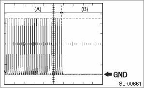
{(AM1 or AM2) -2 V} or more → 1 V or less (waveform 3) |
Steering lock → Steering unlock |
Waveform |
|
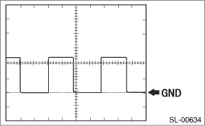
19 (SPD) ←→ Chassis ground |
Pulse generation (waveform 1) |
Driving at approx. 5 km/h |
Waveform |
|
2 (TACH) ←→ Chassis ground |
Pulse generation (waveform 2) |
While engine idling |
Waveform |
|
31 (CTSW) ←→ 6 (GND2) |
1 V or less → {(AM1 or AM2) -2 V} or more |
When clutch pedal depressed, push button ignition switch pressed (while cranking) → Except when cranking |
Voltage |
|
39 (STSW) ←→ 6 (GND2) |
{(AM1 or AM2) -2 V} or more → 1 V or less |
With clutch pedal depressed, and push button ignition switch kept pressing → After one second, release push button ignition switch. |
Voltage |
|
17 (STR1) ←→ 6 (GND2) |
1 V or less → {(AM1 or AM2) -2 V} or more |
Ignition ON |
Voltage |
|
4 (INDS) ←→ 6 (GND2) |
{(AM1 or AM2) -2 V} or more |
Depress clutch pedal. |
Voltage |
|
13 (INDW) ←→ 6 (GND2) |
{(AM1 or AM2) -2 V} or more |
With ACC ON or ignition ON, clutch pedal not depressed |
Voltage |
|
36 (SWIL) ←→ 6 (GND2) |
{(AM1 or AM2) -2 V} or more |
Headlight dimmer switch TAIL or HEAD |
Voltage |
NOTE:
If the measured value is out of standard, it is possible that the power supply CM has a fault.
(1) Waveform 1
|
Item |
Content |
|
Equipment setting |
5 V/DIV, 100 ms/DIV |
(2) Waveform 2
|
Item |
Content |
|
Equipment setting |
5 V/DIV, 100 ms/DIV |
(3) Waveform 3
|
Item |
Content |
|
Equipment setting |
2 V/DIV, 100 ms/DIV |
|
(A) steering lock lock condition |
(B) steering lock unlock condition |
NOTE:
Disconnect the control module connector before checking the following items.
|
Terminal No. |
Standard |
Measuring condition |
Item |
|
10 (+B) ←→ Chassis ground |
0 V→ 10 — 14 V |
Always |
Voltage |
|
1 (IG1) ←→ Chassis ground |
0 V→ 10 — 14 V |
Ignition OFF → Ignition ON |
Voltage |
|
24 (GND) ←→ Chassis ground |
Continuity exists |
Always |
Continuity |
|
20 (ACC) ←→ Chassis ground |
0 V→ 10 — 14 V |
Ignition OFF → ACC ON |
Voltage |
|
3 (MPD1) ←→ Chassis ground |
Pulse generation |
ACC ON or ignition ON |
Input/Output |
|
12 (MPD2) ←→ Chassis ground |
Pulse generation |
ACC ON or ignition ON |
Input/Output |
|
4 (CANL1) ←→ Chassis ground |
Pulse generation |
ACC ON or ignition ON |
Input/Output |
|
5 (CANH1) ←→ Chassis ground |
Pulse generation |
ACC ON or ignition ON |
Input/Output |
|
13 (CANL2) ←→ Chassis ground |
Pulse generation |
ACC ON or ignition ON |
Input/Output |
|
14 (CANH2) ←→ Chassis ground |
Pulse generation |
ACC ON or ignition ON |
Input/Output |
|
15 (WKOUT) ←→ Chassis ground |
8 V or more → 0.5 V or less |
CAN signal sleep status → ACC ON |
Voltage |
|
19 (WKIN) ←→ Chassis ground |
4 V or more → 1.8 V or less |
CAN signal sleep status → Wake up |
Voltage |
NOTE:
If the measured value is out of standard, it is possible that the vehicle harness has a fault.
NOTE:
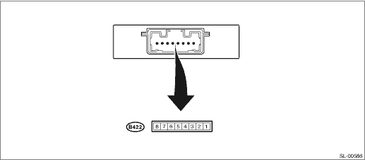
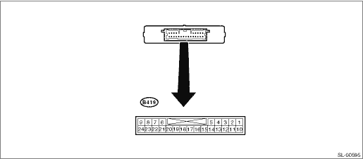
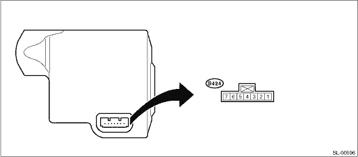
Perform the following check from the back side of the connector, with the connector of the control module connected.
|
Terminal No. |
Standard |
Measuring condition |
Item |
|
1 (GND) ←→ Chassis ground |
Continuity exists |
Always |
Continuity |
|
2 (SGND) ←→ Chassis ground |
Continuity exists |
Always |
Continuity |
|
3 (SLR +) ←→ Chassis ground |
10 — 14 V → 1 V or less |
Motor not operating → Motor operating |
Voltage |
|
4 (SLP) ←→ Chassis ground |
10 — 14 V → 1 V or less |
Lock → Unlock |
Voltage |
|
5 (LIN) |
Input/output signal |
— |
— |
|
6 (IG2) ←→ Chassis ground |
10 — 14 V |
Ignition ON |
Voltage |
|
7 (B) ←→ Chassis ground |
10 — 14 V |
Always |
Voltage |
NOTE:
If the measured value is out of standard, it is possible that the vehicle has a fault.