1.CHECK DTC.
1) Disconnect the ID code box connector.
2) Connect the Subaru Select Monitor and read DTCs.
|
|
|
Replace the ID code box. 
|
2.CHECK DTC.
1) Connect the ID cord box connector, and disconnect the steering lock CM connector.
2) Connect the Subaru Select Monitor and read DTCs.
|
|
|
Replace the steering lock CM.
|
3.CHECK DTC.
1) Connect the steering lock CM connector, and disconnect the power supply CM connector.
NOTE:
By disconnecting the power supply CM connector for inspection, other DTC codes may become detected.
2) Connect the Subaru Select Monitor and read DTCs.
|
Is B2201 or B2217 displayed?
|
|
Replace the power supply CM.
|
4.CHECK COLLATION CM.
1) Connect the power supply CM connector.
2) Disconnect the collation CM connector and the ID cord box connector.
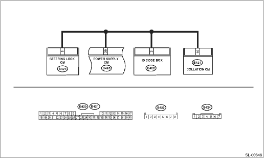
3) Using a tester, check continuity between the collation CM connector and ID cord box connector.
Connector & terminal
(B421) No. 10 — (B422) No. 3:
|
|
|
Repair or replace the open circuit of harness.
|
5.CHECK COLLATION CM.
Using a tester, check continuity between the collation CM connector and chassis ground.
Connector & terminal
(B421) No. 10 — Chassis ground:
|
|
Repair or replace the short circuit of the harness.
|
|
6.CHECK COLLATION CM.
1) Disconnect the collation CM connector and the steering lock CM connector.
2) Using a tester, check continuity between the collation CM connector and steering lock CM connector.
Connector & terminal
(B421) No. 10 — (B424) No. 5:
|
|
|
Repair or replace the open circuit of harness.
|
7.CHECK HARNESS.
Using a tester, check continuity between the steering lock CM connector and chassis ground.
Connector & terminal
(B424) No. 5 — Chassis ground:
|
|
Repair or replace the short circuit of the harness.
|
|
8.CHECK COLLATION CM.
1) Connect the steering lock CM connector.
2) Disconnect the collation CM connector and power supply CM connector.
3) Using a tester, check continuity between the collation CM connector and power supply CM connector.
Connector & terminal
(B421) No. 10 — (B420) No. 30:
|
|
|
Repair or replace the open circuit of harness.
|
9.CHECK HARNESS.
Using a tester, check continuity between the power supply CM connector and chassis ground.
Connector & terminal
(B420) No. 30 — Chassis ground:
|
|
Repair or replace the short circuit of the harness.
|
Replace the collation CM.
|