DTC DETECTING CONDITION:
The power supply CM engine start request output circuit is open or shorted.
TROUBLE SYMPTOM:
Engine will not start.
CAUTION:
When the power supply CM is replaced with a new unit, and the battery ground terminal is connected, it will become ignition ON. Also, if the battery is disconnected, it will resume to a condition with the battery cut off.
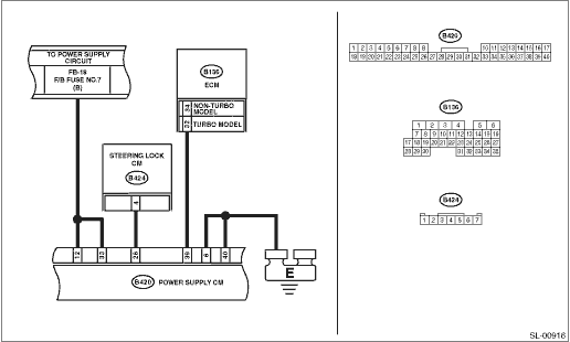
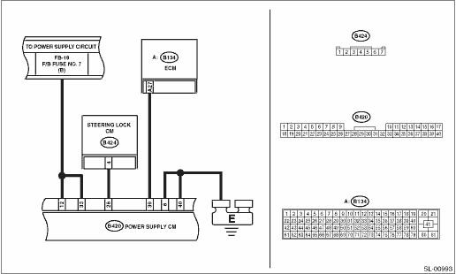
WIRING DIAGRAM:
• Gasoline engine model

• Diesel engine model
| STEP | CHECK | YES | NO |
|
Is the fuse blown out? |
Replace the fuse (FB-18). If the replaced fuse has blown out easily, repair the short circuit in the harness between the fuse holder and the power supply CM. |
|
|
|
Is the voltage 10 V or more? |
|
Repair the open circuit or short in the harness between the power supply CM and the fuse. |
|
|
Is there continuity? |
|
Repair or replace the open circuit location in the wiring harness. |
|
|
1) Disconnect the ECM connector (B136) and power supply CM connector. 2) Using a tester, check continuity between the ECM connector and the power supply CM connector. Connector & terminal Turbo model (B420) No. 39 (+) — (B136) No. 32 (−): Non-turbo model (B420) No. 39 (+) — (B136) No. 34 (−): Diesel engine model (B420) No. 39 (+) — (B134) No. 27 (−): |
Is there continuity? |
|
Repair or replace the open circuit of harness. |
|
Is there continuity? |
Repair or replace the open circuit of harness. |
|
|
|
Is B2104 (Steering lock position signal error) displayed? |
Perform the diagnosis according to the DTC. |
|
|
|
Is there continuity? |
|
Check the steering lock. |
|
|
Does the voltage change from less than 1 V → 2 V or more? |
Perform fault diagnosis for the engine system. |
Replace the power supply CM. |
