1. HOW TO USE SUBARU SELECT MONITOR
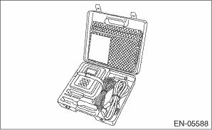
1. Prepare the Subaru Select Monitor kit. 
2. Prepare the personal computer which has been installed the Subaru Select Monitor.
3. Connect the SDI (Subaru Diagnostic Interface) to the PC USB port (exclusively for Subaru Selector Monitor) using a USB cable.
NOTE:
The dedicated port for the Subaru Select Monitor means the USB port which was used to install the Subaru Select Monitor.
4. Connect the diagnosis cable to the SDI.
5. Connect the SDI to the data link connector located in the lower portion of the instrument panel (on the driver’s side).
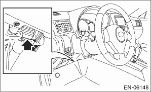
CAUTION:
Do not connect any scan tools other than the Subaru Select Monitor.
6. Start the PC.
7. Turn the ignition switch to ON (engine OFF), and run the “PC application for Subaru Select Monitor”.
8. Record the DTC and data.
NOTE:
For detailed operation procedure, refer to the “PC application help for Subaru Select Monitor”.
9. If the power steering control module and Subaru Select Monitor can not communicate, check the communication circuit.
1. On «Main Menu» display, select {Each System Check}.
2. On «System Selection Menu» display, select {Power Steering}.
3. On «Power Steering Diagnosis» display, select {Current Data Display & Save}.
4. Using the scroll keys, move the screen up or down until the desired data is displayed.
The list is indicated in the following table.
|
Display |
Contents to be displayed |
Range |
Unit |
|
Torque Sensor main |
Main torque sensor output voltage is displayed. |
0 — 5 |
V |
|
Torque Sensor sub |
Sub torque sensor output voltage is displayed. |
0 — 5 |
V |
|
Torque Sensor Control Value |
Torque sensor control voltage is displayed. |
0 — 5 |
V |
|
Actual motor current |
The current flowing to the motor relay is displayed. |
−128 — 127 |
A |
|
Vehicle Speed |
Vehicle speed is displayed. (CAN communication data) |
0 — 255 |
km/h |
|
Engine Speed |
Engine speed is displayed. (CAN communication data) |
0 — 12750 |
rpm |
|
Motor Current Value |
The current trying to be sent to the motor is displayed. |
−128 — 127 |
Arms |
|
Motor phase-V current |
The required assist current command value calculated by the microcomputer from the torque sensor input is displayed. |
−128 — 127 |
Arms |
|
Motor phase-W current |
The required assist current command value calculated by the microcomputer from the torque sensor input is displayed. |
−128 — 127 |
Arms |
|
Motor angle |
Data from the resolver sensor is displayed. |
0 — 359 |
deg |
|
Motor angular speed |
Data from the resolver sensor is displayed. |
−4096 — 4064 |
rpm |
|
Thermistor Temperature |
The thermistor temperature of the steering control module is displayed. |
−50 — 205 |
°C |
|
Power Supply Voltage |
Battery voltage is displayed. |
0 — 25.5 |
V |
|
Torque sensor voltage |
The power supply voltage output to the torque sensor is displayed. |
0 — 5 |
V |
|
IG voltage |
The power supply voltage supplied to the ECM is displayed. |
0 — 15 |
V |
|
CAN bus status |
Either Active/Passive/Bus Off is displayed. |
Active |
— |
|
EPS operation flag |
Either Normal/Assist Stop/Assist Restricted is displayed. |
Normal |
— |
|
Motor voltage (target) |
The motor target current value required for assist is displayed. |
−128 — 127 |
A |
NOTE:
For detailed operation procedures, refer to “PC application help for Subaru Select Monitor”.
NOTE:
• Freeze frame data stored at the time of trouble occurrence is shown on the display.
• Each time a trouble occurs, the latest information is stored in the freeze frame data in memory.
• Up to 3 freeze frame data will be stored.
|
Display |
Contents to be displayed |
|
Latest |
The current DTC is displayed on Subaru Select Monitor display screen. |
|
Old |
DTCs for previous malfunctions are displayed on the Subaru Select Monitor screen. |
|
Older |