LAN SYSTEM (DIAGNOSTICS) > Diagnostic Procedure with Diagnostic Trouble Code (DTC)

DTC B1105 KEY INTERLOCK CIRCUIT ABNORMAL

DTC DETECTING CONDITION:

Open or short in key interlock circuit

TROUBLE SYMPTOM:

Key interlock does not keep lock condition.
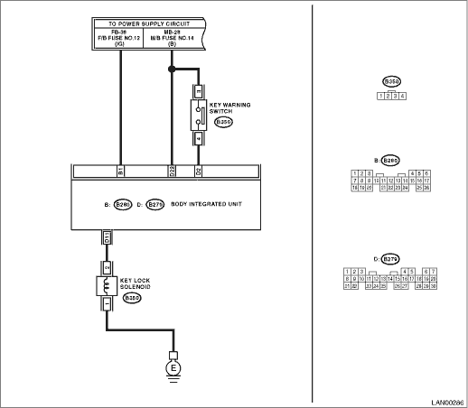
WIRING DIAGRAM:

STEPCHECKYESNO

1.CHECK DTC.

1) Insert the ignition key.

2) Shift to the Neutral range.

3) Read the DTC of body integrated unit using Subaru Select Monitor.

Is B1105 current malfunction?

2.CHECK DTC.

1) Remove the ignition key.

2) Disconnect the key lock solenoid connector (B350) and body integrated unit connector (B279).

3) Connect the disconnected connectors.

4) Turn the ignition switch to ON and shift into Neutral.

5) Read the DTC of body integrated unit using Subaru Select Monitor.

Is B1105 current malfunction?

3.CHECK KEY LOCK SOLENOID.

1) Disconnect the key lock solenoid connector (B350).

2) Measure the resistance between the key lock solenoid connector.

Connector & terminal

(B350) No. 1 — No. 2:

Is the resistance between 12 — 14.5 Ω?

Replace the key lock solenoid.

4.CHECK KEY LOCK SOLENOID.

1) Turn the ignition switch to OFF.

2) Disconnect the key lock solenoid connector.

3) Connect the battery terminal to key lock solenoid.

Terminals

(B350) No. 2 — positive terminal:
(B350) No. 1 — ground terminal:

Is the solenoid activated and then key locked?

Replace the key lock solenoid.

5.CHECK HARNESS.

1) Disconnect the body integrated unit connector (B279).

2) Measure the resistance between body integrated unit and key lock solenoid using tester.

Connector & terminal

(B350) No. 2 — (B279) No. 11:

Is the resistance less than 10 Ω?

Repair or replace the open circuit of harness.

6.CHECK HARNESS.

Measure the resistance between body integrated unit and chassis ground using tester.

Connector & terminal

(B279) No. 11 — Chassis ground:

Is the resistance 1 MΩ or more?

Repair or replace the short circuit of the harness.

7.CHECK HARNESS.

1) Turn the ignition switch to ON.

2) Measure the voltage between body integrated unit and chassis ground using tester.

Connector & terminal

(B279) No. 11 (+) — Chassis ground (−):

Is the voltage 1.5 V or more?

Repair or replace the short circuit of the harness.

Replace the body integrated unit.

8.CHECK CONNECTOR.

1) Turn the ignition switch to OFF.

2) Disconnect the body integrated unit connector (B279) and key lock solenoid connector (B350).

Is there poor contact at disconnected connector terminal?

Repair the terminal where poor contact exists, or replace harness.

It is possible that temporary poor contact occurs.