|
|
Is the ignition switch ON?
|
|
Turn the ignition switch to ON, and select Integ. unit mode using Subaru Select Monitor.
|
2.CHECK BATTERY.
1) Turn the ignition switch to OFF.
2) Measure the battery voltage.
|
Is the voltage 11 V or more?
|
|
Charge or replace the battery.
|
3.CHECK BATTERY TERMINAL.
|
Is there poor contact at the battery terminal?
|
Repair or tighten the battery terminal.
|
|
4.CHECK COMMUNICATION OF SUBARU SELECT MONITOR.
1) Turn the ignition switch to ON.
2) Using the Subaru Select Monitor, check whether communication to other systems can be executed normally.
|
Is the system name displayed?
|
|
|
5.CHECK COMMUNICATION OF SUBARU SELECT MONITOR.
1) Turn the ignition switch to OFF.
2) Disconnect the body integrated unit connector.
3) Turn the ignition switch to ON.
4) Check whether communication to other systems can be executed normally.
|
Is the system name displayed?
|
|
|
6.CHECK HARNESS CONNECTOR BETWEEN EACH CONTROL MODULE AND SUBARU SELECT MONITOR.
1) Turn the ignition switch to ON.
2) Disconnect the body integrated unit connector.
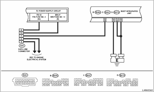
3) Measure the resistance between data link connector and chassis ground.
Connector & terminal
(B40) No. 7 — Chassis ground:
|
Is the resistance 1 MΩ or more?
|
|
Repair the harness and connector between each control module and Subaru Select Monitor.
|
7.CHECK OUTPUT SIGNAL TO BODY INTEGRATED UNIT.
1) Turn the ignition switch to ON.
2) Measure the voltage between body integrated unit and chassis ground.
Connector & terminal
(B40) No. 7 (+) — Chassis ground (−):
|
Is the voltage less than 1 V?
|
|
Repair the harness and connector between each control module and Subaru Select Monitor.
|
8.CHECK HARNESS CONNECTOR BETWEEN BODY INTEGRATED UNIT AND DATA LINK CONNECTOR.
Measure the resistance between body integrated unit and data link connector.
Connector & terminal
(B40) No. 7 — (B280) No. 20:
|
Is the resistance less than 1 Ω?
|
|
Repair the harness and connector between body integrated unit and Subaru Select Monitor.
|
9.CHECK BACK-UP FUSE.
Check that back-up fuse is not blown out, or check that it is inserted.
|
|
|
Replace the back-up fuse, or insert it into the fuse holder.
|
10.CHECK POWER SUPPLY CIRCUIT.
1) Turn the ignition switch to ON (engine OFF).
2) Measure the ignition voltage between body integrated unit connector and chassis ground.
Connector & terminal
(B280) No. 1 (+) — Chassis ground (−):
|
Is the voltage 10 V or more?
|
|
Repair the open circuit of harness between body integrated unit and battery.
|
11.CHECK HARNESS CONNECTOR BETWEEN BODY INTEGRATED UNIT AND CHASSIS GROUND.
1) Turn the ignition switch to OFF.
2) Disconnect the connector from body integrated unit.
3) Measure the resistance of harness between the body integrated unit and chassis ground.
Connector & terminal
(B280) No. 20 — Chassis ground:
|
Is the resistance 1 MΩ or more?
|
|
Repair the poor contact of harness between body integrated unit and ground.
|
12.CHECK POOR CONTACT OF CONNECTOR.
|
Is there poor contact at control module ground and Subaru Select Monitor?
|
Replace the body integrated unit. 
|
Repair the poor contact of connector.
|