1.CHECK BODY INTEGRATED UNIT POWER SUPPLY CIRCUIT.
1) Turn the ignition switch to OFF.
2) Disconnect the harness connector from body integrated unit.
3) Measure the voltage between the body integrated unit harness connector terminal and chassis ground.
Connector & terminal
(B280) No. 6 (+) — Chassis ground (−):
|
Is the voltage 10 V or more?
|
|
Check the harness for open or short circuit between the body integrated unit and fuse.
|
2.CHECK BODY INTEGRATED UNIT POWER SUPPLY CIRCUIT.
1) Turn the ignition switch to ON. (engine OFF)
2) Measure the voltage between the body integrated unit harness connector terminal and chassis ground.
Connector & terminal
(B280) No. 1 (+) — Chassis ground (−):
|
Is the voltage 10 V or more?
|
|
Check the harness for open or short circuit between the body integrated unit and ignition switch.
|
3.CHECK BODY INTEGRATED UNIT GROUND CIRCUIT.
1) Turn the ignition switch to OFF.
2) Measure the resistance between body integrated unit harness connector terminal and chassis ground.
Connector & terminal
(B280) No. 17 — Chassis ground:
(B281) No. 20 — Chassis ground:
(B279) No. 27 — Chassis ground:
|
Is the resistance less than 10 Ω?
|
|
Repair the open circuit of the body integrated unit ground circuit.
|
4.CHECK GROUND CIRCUIT FOR ECM.
Measure the resistance between the ECM ground terminal and engine ground.
|
Is the resistance less than 10 Ω?
|
|
Repair ground circuit of ECM.
|
5.CHECK HARNESS BETWEEN BODY INTEGRATED UNIT AND ECM.
1) Disconnect the harness connector from the ECM and body integrated unit.
2) Measure the resistance between body integrated unit harness connector terminal and ECM harness connector terminal.
Connector & terminal
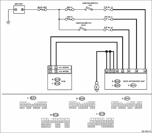
2.5 L model:
(B280) No. 4 — (B136) No. 26:
2.0 L model:
(B280) No. 4 — (B135) No. 11:
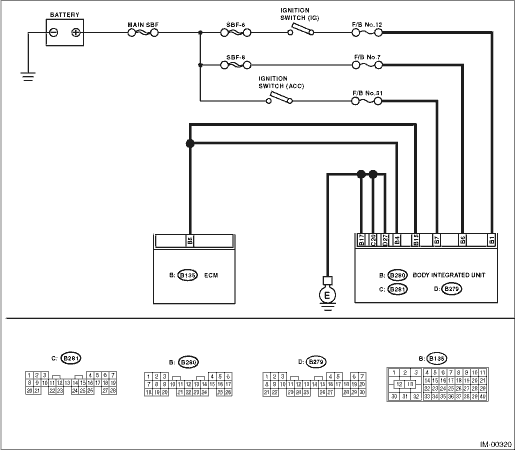
Diesel engine model:
(B280) No. 4 — (B135) No. 5:
|
Is the resistance less than 10 Ω?
|
|
Repair the open circuit of the harness between the body integrated unit and ECM.
|
6.CHECK HARNESS BETWEEN BODY INTEGRATED UNIT AND ECM.
Measure the resistance between body integrated unit harness connector terminal and ECM harness connector terminal.
Connector & terminal
2.5 L model:
(B280) No. 15 — (B136) No. 34:
2.0 L model:
(B280) No. 15 — (B135) No. 12:
Diesel engine model:
(B280) No. 15 — (B135) No. 5:
|
Is the resistance less than 10 Ω?
|
|
Repair the open circuit of the harness between the body integrated unit and ECM.
|
7.CHECK COMMUNICATION CIRCUIT HARNESS.
1) Turn the ignition switch to ON. (engine OFF)
2) Measure the voltage between the body integrated unit harness connector terminal and chassis ground.
Connector & terminal
(B280) No. 4 (+) — Chassis ground (−):
(B280) No. 15 (+) — Chassis ground (−):
|
|
|
Because the battery voltage or ignition switch “ON” circuit is shorted, repair the harness between the body integrated unit and ECM.
|
8.CHECK COMMUNICATION CIRCUIT HARNESS.
Measure the voltage between ECM harness connector terminal and engine ground.
Connector & terminal
2.5 L model
(B136) No. 26 (+) — Engine ground (−):
(B136) No. 34 (+) — Engine ground (−):
2.0 L model
(B135) No. 11 (+) — Engine ground (−):
(B135) No. 12 (+) — Engine ground (−):
Diesel engine model
(B135) No. 5 (+) — Engine ground (−):
|
|
|
Because the battery voltage or ignition switch “ON” circuit is shorted, repair the harness between the body integrated unit and ECM.
|
9.CHECK ECM BY COMMUNICATION LINE CHECK.
1) Connect the harness connector to ECM.
2) Disconnect the harness connector from body integrated unit.
3) Start the communication line short check. 
|
Is the communication line check OK?
|
Replace the body integrated unit, replace all ignition keys (including the transponder). Execute the registration procedure next. Refer to the “PC application help for Subaru Select Monitor”.
|
Replace the ECM. Perform the registration procedure next. Refer to the “PC application help for Subaru Select Monitor”.
|