IMMOBILIZER (DIAGNOSTICS) > Diagnostics Chart for Security Indicator Light

INSPECTION

1. CHECK SECURITY INDICATOR LIGHT CIRCUIT
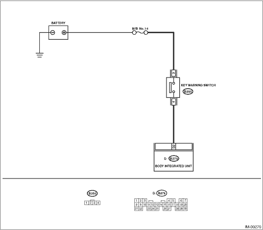
WIRING DIAGRAM:

STEPCHECKYESNO

1.CHECK FUSE.

1) Turn the ignition switch to OFF.

2) Check the fuse (M/B No. 8).

Is the fuse blown out?

Replace the fuse. If the replaced fuse blows out easily, repair the short circuit in the harness between the fuse and body integrated unit.

2.CHECK SECURITY INDICATOR LIGHT.

1) Turn the ignition switch to OFF.

2) Disconnect the harness connector from body integrated unit.

3) Connect the resistor (100 Ω) between the body integrated unit harness connector terminal (i84) No. 10 and chassis ground.

Does the security indicator light illuminate?

3.CHECK BODY INTEGRATED UNIT GROUND CIRCUIT.

Measure the resistance between body integrated unit harness connector terminal and chassis ground.

Connector & terminal

(i84) No. 28 — Chassis ground:

(B280) No. 17 — Chassis ground:

(B281) No. 20 — Chassis ground:

(B279) No. 27 — Chassis ground:

Is the resistance less than 10 Ω?

Repair the open circuit of the body integrated unit ground circuit.

4.CHECK BODY INTEGRATED UNIT IGNITION CIRCUIT.

1) Turn the ignition switch to ON. (engine OFF)

2) Measure the voltage between the body integrated unit harness connector terminal and chassis ground.

Connector & terminal

(B280) No. 1 (+) — Chassis ground (−):

Is the voltage 10 V or more?

Check the harness for open or short circuit between the body integrated unit and ignition switch.

5.CHECK BODY INTEGRATED UNIT POWER SUPPLY CIRCUIT.

1) Turn the ignition switch to OFF.

2) Measure the voltage between the body integrated unit harness connector terminal and chassis ground.

Connector & terminal

(B280) No. 6 (+) — Chassis ground (−):

(B281) No. 2 (+) — Chassis ground (−):

Is the voltage 10 V or more?

Replace the body integrated unit, replace all ignition keys (including the transponder). Execute the registration procedure next. Refer to the “PC application help for Subaru Select Monitor”.

Check the harness for open or short circuit between the body integrated unit and fuse.

6.CHECK COMBINATION METER CIRCUIT.

1) Remove the combination meter.

2) Measure the voltage between combination meter harness connector terminal and chassis ground.

Connector & terminal

(i10) No. 1 (+) — Chassis ground (−):

Is the voltage 10 V or more?

Check for an open or short circuit in the harness between the combination meter and fuse.

7.CHECK COMBINATION METER CIRCUIT.

Measure the resistance between the body integrated unit harness connector terminal and combination meter harness connector terminal.

Connector & terminal

(i84) No. 10 — (i10) No. 39:

Is the resistance less than 10 Ω?

LED bulb is defective. Replace the combination meter case assembly.

Repair the harness or connector.
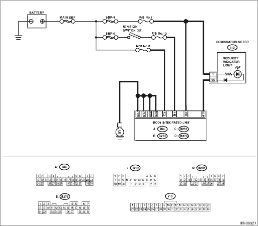
2. CHECK KEY SWITCH CIRCUIT

WIRING DIAGRAM:

STEPCHECKYESNO

1.CHECK POWER SUPPLY CIRCUIT.

1) Disconnect the key warning switch harness connector.

2) Set the ignition switch to ACC or LOCK (with key inserted).

3) Measure the voltage between the key warning switch harness connector terminal and chassis ground.

Connector & terminal

(B350) No. 3 (+) — Chassis ground (−):

Is the voltage 10 V or more?

Check for an open or short circuit in the harness between the key warning switch and fuse.

2.CHECK KEY WARNING SWITCH.

1) Insert the ignition key in the ignition switch. (OFF or ACC)

2) Measure the resistance between key warning switch connector terminals.

Connector & terminal

No. 3 — No. 4:

Is the resistance less than 1 Ω?

Replace the key warning switch.

3.CHECK KEY WARNING SWITCH.

1) Remove the ignition key from the ignition switch.

2) Measure the resistance between key warning switch connector terminals.

Connector & terminal

No. 3 — No. 4:

Is the resistance 1 MΩ or more?

Replace the key warning switch.

4.CHECK HARNESS BETWEEN KEY WARNING SWITCH AND BODY INTEGRATED UNIT.

1) Disconnect the key warning switch harness connector.

2) Disconnect the harness connector from the body integrated unit.

3) Measure the resistance between the key warning switch harness connector and body integrated unit harness connector terminals.

Connector & terminal

(B350) No. 4 — (B279) No. 2:

Is the resistance less than 10 Ω?

Replace the body integrated unit, Replace all ignition keys (including the transponder). Execute the registration procedure next. Refer to the “PC application help for Subaru Select Monitor”.

Repair the harness between the key warning switch and body integrated unit.