1.CHECK POWER SUPPLY TO FRONT OXYGEN (A/F) SENSOR.
1) Turn the ignition switch to OFF.
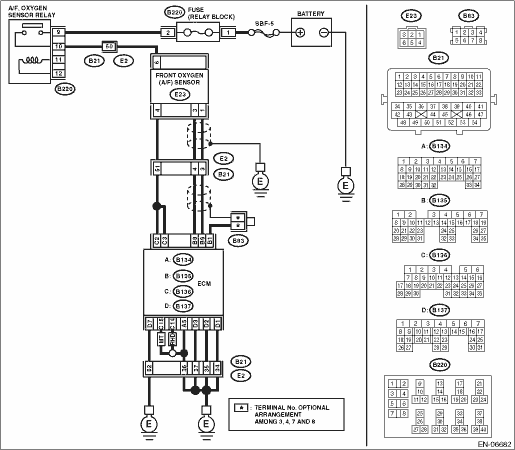
2) Disconnect the connector from front oxygen (A/F) sensor.
3) Turn the ignition switch to ON.
4) Measure the voltage between front oxygen (A/F) sensor connector and engine ground.
Connector & terminal
(E23) No. 6 (+) — Engine ground (−):
|
Is the voltage 10 V or more?
|
|
Repair the power supply line.
NOTE:
In this case, repair the following item:
• Open circuit in harness between A/F, oxygen sensor relay and front oxygen (A/F) sensor
• Poor contact of A/F, oxygen sensor relay connector
• Poor contact of coupling connector
|
2.CHECK HARNESS BETWEEN ECM AND FRONT OXYGEN (A/F) SENSOR.
1) Turn the ignition switch to OFF.
2) Disconnect the connectors from the ECM.
3) Measure the resistance between ECM and front oxygen (A/F) sensor connector.
Connector & terminal
(B136) No. 2 — (E23) No. 4:
(B136) No. 3 — (E23) No. 4:
|
Is the resistance less than 1 Ω?
|
|
Repair the harness and connector.
NOTE:
In this case, repair the following item:
• Open circuit in harness between ECM and front oxygen (A/F) sensor
• Poor contact of coupling connector
|
3.CHECK GROUND CIRCUIT FOR ECM.
Measure the resistance of harness between ECM and chassis ground.
Connector & terminal
(B134) No. 5 — Chassis ground:
(B137) No. 1 — Chassis ground:
(B137) No. 2 — Chassis ground:
(B137) No. 3 — Chassis ground:
(B137) No. 7 — Chassis ground:
MT model
(B136) No. 15 — Chassis ground:
RHD model
(B136) No. 14 — Chassis ground:
|
Is the resistance less than 5 Ω?
|
|
Repair the harness and connector.
NOTE:
In this case, repair the following item:
• Open circuit of harness between ECM and engine ground
• Poor contact of coupling connector
|
4.CHECK FRONT OXYGEN (A/F) SENSOR.
Measure the resistance between front oxygen (A/F) sensor terminals.
|
Is the resistance between 2 — 3 Ω?
|
Repair the poor contact of the ECM connector.
|
Replace the front oxygen (A/F) sensor. 
|