1.CHECK POOR CONTACT OF CONNECTOR.
Check if there is poor contact between VDCCM&H/U and ABS wheel speed sensor.
|
|
|
|
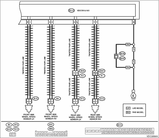
2.CHECK HARNESS CONNECTOR BETWEEN VDCCM&H/U AND ABS WHEEL SPEED SENSOR.
1) Disconnect the connector (B310) from the VDCCM&H/U.
2) Disconnect the connector from the ABS wheel speed sensor.
3) Measure the resistance between VDCCM&H/U connector and ABS wheel speed sensor connector.
Connector & terminal
DTC C0021
(B310) No. 6 — (B6) No. 1:
(B310) No. 5 — (B6) No. 2:
DTC C0023
(B310) No. 1 — (B15) No. 1:
(B310) No. 26 — (B15) No. 2:
DTC C0025
(B310) No. 3 — (R72) No. 2:
(B310) No. 4 — (R72) No. 1:
DTC C0027
(B310) No. 2 — (R73) No. 2:
(B310) No. 27 — (R73) No. 1:
|
Is the resistance less than 0.5 Ω?
|
|
Repair the harness connector between VDCCM&H/U and ABS wheel speed sensor.
|
3.CHECK GROUND SHORT OF HARNESS.
Measure the resistance between VDCCM&H/U connector and chassis ground.
Connector & terminal
DTC C0021
(B310) No. 6 — Chassis ground:
DTC C0023
(B310) No. 1 — Chassis ground:
DTC C0025
(B310) No. 4 — Chassis ground:
DTC C0027
(B310) No. 27 — Chassis ground:
|
Is the resistance 1 MΩ or more?
|
|
Repair the harness connector between VDCCM&H/U and ABS wheel speed sensor.
|
4.CHECK ABS WHEEL SPEED SENSOR POWER SUPPLY CIRCUIT.
1) Connect the VDCCM&H/U connector.
2) Turn the ignition switch to ON.
3) Measure the voltage between ABS wheel speed sensor connector and chassis ground.
Connector & terminal
DTC C0021
(B6) No. 2 (+) — Chassis ground (−):
DTC C0023
(B15) No. 2 (+) — Chassis ground (−):
DTC C0025
(R72) No. 2 (+) — Chassis ground (−):
DTC C0027
(R73) No. 2 (+) — Chassis ground (−):
|
|
|
|
5.CHECK VDCCM&H/U POWER SUPPLY CIRCUIT.
1) Turn the ignition switch to OFF.
2) Disconnect the VDCCM&H/U connector.
3) Turn the ignition switch to ON.
4) Measure the voltage between VDCCM&H/U connector terminals.
Connector & terminal
(B310) No. 28 (+) — (B310) No. 25 (−):
|
Is the voltage 10 — 15 V?
|
|
Check the generator, battery and VDCCM&H/U power supply circuit.
|
6.CHECK ABS WHEEL SPEED SENSOR SIGNAL.
1) Install the ABS wheel speed sensor.
2) Prepare an oscilloscope.
3) Check the ABS wheel speed sensor. 
|
Is the pattern the same waveform as shown in the figure?
|
|
Replace the ABS wheel speed sensor.
|
7.CHECK VDCCM&H/U.
1) Connect all connectors.
2) Clear the memory.
3) Perform the Inspection Mode.
|
Is the same DTC displayed?
|
Replace the VDCCM only.
|
|
8.CHECK OTHER DTC DETECTION.
|
Is any other DTC displayed?
|
Perform the diagnosis according to DTC.
|
It results from a temporary noise interference.
|