1. HOW TO USE THE SUBARU SELECT MONITOR
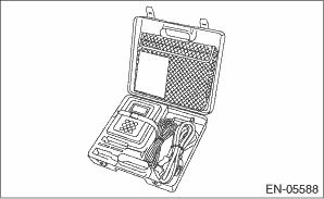
1. Prepare the Subaru Select Monitor kit. 
2. Prepare PC with Subaru Select Monitor installed.
3. Connect the USB cable between SDI (Subaru Diagnosis Interface) and USB port on the personal computer (dedicated port for the Subaru Select Monitor).
NOTE:
The dedicated port for the Subaru Select Monitor means the USB port which was used to install the Subaru Select Monitor.
4. Connect the diagnosis cable to SDI.
5. Connect SDI to data link connector located in the lower portion of the instrument panel (on the driver’s side).
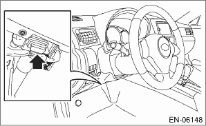
CAUTION:
Do not connect scan tools other than the Subaru Select Monitor.
6. Start the PC.
7. Turn the ignition switch to ON (engine OFF) and run the “PC application for Subaru Select Monitor”.
NOTE:
For detailed operation procedures, refer to “PC application help for Subaru Select Monitor”.
8. If VDC and Subaru Select Monitor cannot communicate, check the communication circuit.
1. On «Main Menu» display, select {Each System Check}.
2. On «System Selection Menu» display, select {Brake Control System}.
3. Click the [OK] button after the {VDC} is displayed.
4. On «Brake Control Diagnosis» display, select {Current Data Display & Save}.
5. On «Data Display Menu» display, select the data display method.
6. Using the scroll key, scroll the display screen up or down until necessary data is shown.
• A list of the support data is shown in the following table.
|
Display |
Contents to be monitored |
Unit of measure |
|
FR Wheel Speed |
Wheel speed detected by front ABS wheel speed sensor RH is displayed. |
km/h or MPH |
|
FL Wheel Speed |
Wheel speed detected by front ABS wheel speed sensor LH is displayed. |
km/h or MPH |
|
RR Wheel Speed |
Wheel speed detected by rear ABS wheel speed sensor RH is displayed. |
km/h or MPH |
|
RL Wheel Speed |
Wheel speed detected by rear ABS wheel speed sensor LH is displayed. |
km/h or MPH |
|
Steering Angle Sensor Op |
Steering angle detected by steering angle sensor is displayed. |
deg |
|
Yaw Rate Sensor Output |
Vehicle angular speed detected by yaw rate sensor is displayed. |
deg/s |
|
Pressure Sensor Output |
Brake fluid pressure detected by pressure sensor is displayed. |
bar |
|
Lateral G sensor Output |
Vehicle lateral acceleration detected by lateral G sensor is displayed. |
m/s2 |
|
IG power supply voltage |
Voltage supplied to VDCCM&H/U is displayed. |
V |
|
E/G Control Stop Flag |
Engine control command signal is displayed. |
1 or 0 |
|
ABS Control Flag |
ABS operation condition is displayed. |
ON or OFF |
|
EBD Control Flag |
EBD operation condition is displayed. |
ON or OFF |
|
TCS Control Flag |
TCS operation condition is displayed. |
ON or OFF |
|
VDC Control Flag |
VDC operation condition is displayed. |
ON or OFF |
|
OFF Lamp |
ON/OFF condition of VDC OFF indicator light is displayed. |
ON or OFF |
|
EBD Warning Light |
ON operation of the EBD warning light is displayed. |
ON or OFF |
|
ABS Warning Light |
ON operation of the ABS warning light is displayed. |
ON or OFF |
|
VDC Warning Light |
ON operation of the VDC warning light is displayed. |
ON or OFF |
|
Valve Relay Signal |
Valve relay operation signal is displayed. |
ON or OFF |
|
Motor Relay Signal |
Motor relay operation signal is displayed. |
ON or OFF |
|
M. Relay monitor Voltage |
Voltage applied to the motor relay is displayed. |
V |
|
OFF SW Signal |
Operation condition of VDC OFF switch is displayed. |
ON or OFF |
|
Brake Switch |
Brake ON/OFF is displayed. |
ON or OFF |
|
Longitudinal G sensor output |
Vehicle longitudinal acceleration detected by longitudinal G sensor is displayed. (For MT vehicle only. For AT vehicle: At −0.1 m/s2 constantly) |
m/s2 |
|
Clutch Switch |
Clutch ON/OFF is displayed. (For MT vehicle only. For AT vehicle: OFF fixed) |
ON or OFF |
|
Reverse Signal |
Reverse gear ON/OFF is displayed. (For MT vehicle only. For AT vehicle: OFF fixed) |
ON or OFF |
NOTE:
For detailed operation procedures, refer to “PC application help for Subaru Select Monitor”.
|
Display |
Contents of display |
Index No. |
|
ABS Sequence Control Mode |
Operate the valve and pump motor continuously to perform the ABS sequence control. |
|
|
VDC Check Mode |
Operate the valve and pump motor continuously to perform the VDC sequence control. |
|
|
Set up mode for Neutral of Steering Angle Sensor & Lateral G Sensor 0 point |
Set the steering angle sensor neutral position and the lateral G sensor “0” point. |
|
NOTE:
• Data stored at the time of trouble occurrence is shown on display.
• Each time a trouble occurs, the latest information is stored in the freeze frame data in memory.
• If a freeze frame data is not properly stored in memory (due to a drop in VDCCM power supply, etc.), a DTC suffixed with a question mark “?” appears on the Subaru Select Monitor display. This shows it may be an unreliable reading.
|
Display |
Contents to be monitored |
|
Steering Angle Sensor Op |
Steering angle detected by steering angle sensor is displayed. |
|
Yaw Rate Sensor Output |
Vehicle angular speed detected by yaw rate sensor is displayed. |
|
Lateral G sensor Output |
Vehicle lateral acceleration detected by lateral G sensor is displayed. |
|
Pressure Sensor Output |
Brake fluid pressure detected by pressure sensor is displayed. |
|
Vehicle Speed |
Vehicle speed calculated by VDC control module is displayed. |
|
FR Wheel Speed |
Wheel speed detected by front ABS wheel speed sensor RH is displayed in km/h or MPH. |
|
FL Wheel Speed |
Wheel speed detected by front ABS wheel speed sensor LH is displayed in km/h or MPH. |
|
RR Wheel Speed |
Wheel speed detected by rear ABS wheel speed sensor RH is displayed in km/h or MPH. |
|
RL Wheel Speed |
Wheel speed detected by rear ABS wheel speed sensor LH is displayed in km/h or MPH. |
|
Accel. Opening Angle |
Acceleration opening is displayed. |
|
Engine Speed |
Engine speed on malfunction occurrence is displayed. |
|
Gear Position |
Gear position on malfunction occurrence is displayed. |
|
IG power supply voltage |
Voltage supplied to VDC control module is displayed. |
|
Steering angle flag |
Whether the absolute angle of the steering angle sensor was determined is displayed. |
|
E/G Control Stop Flag |
Engine control command signal is displayed. |
|
VDC Control Flag |
VDC control condition is displayed. |
|
EBD Control Flag |
EBD control condition is displayed. |
|
TCS Control Flag |
TCS control condition is displayed. |
|
ABS Control Flag |
ABS control condition is displayed. |
|
OFF Switch Detection |
ON/OFF condition of the VDC operated by the driver is displayed. |
|
Brake Switch |
Brake ON/OFF is displayed. |
|
Longitudinal G sensor output |
Vehicle longitudinal acceleration detected by longitudinal G sensor is displayed. (For MT vehicle only. For AT vehicle: At −0.1 m/s2 constantly) |
|
Clutch Switch |
Clutch ON/OFF is displayed. (For MT vehicle only. For AT vehicle: OFF fixed) |
|
Reverse Signal |
Reverse gear ON/OFF is displayed. (For MT vehicle only. For AT vehicle: OFF fixed) |
CAUTION:
• Subaru Select Monitor is required for parameter selection.
• This function can be used for the replacement VDCCM&H/U and VDCCM.
NOTE:
• When a VDCCM is replaced with a replacement, use this function to select and register parameters to the VDCCM.
• For confirmation of applied models, refer to the “Model number plate” attached to the vehicles.
• If a wrong applied model is written, it can be rewritten.
• When no data is registered, ABS/EBD/VDC warning light illuminates and the DTC “Parameter selection error” is detected.
1. Connect the Subaru Select Monitor.
2. On the «Main Menu» display, select {Each System Check}.
3. On the «System Selection Menu», select {Brake Control System}.
4. Click the [OK] button after the {VDC} is displayed.
5. On the «Brake Control Diagnosis», select {Selection of Parameter}.
6. Check the applied model indicated in the “Model number plate”.
7. Enter the applied model of 7-digit alphanumeric characters and press the [Enter] key.
8. When the confirmation screen indicating the vehicle information appears, check that the correct applied model and grade are displayed and click the [OK] button.
NOTE:
When the displayed applied model and grade are different from those of the vehicle, perform registration operations again after clicking the [OK] button.
9. Execute Clear Memory after parameter selection and registration operations because the DTC for “Parameter selection error” is memorized.
NOTE:
The parameter data registered in the VDCCM is shown on the display.
1. Connect the Subaru Select Monitor.
2. On the «Main Menu» display, select {Each System Check}.
3. On the «System Selection Menu», select {Brake Control System}.
4. Click the [OK] button after the {VDC} is displayed.
5. On the «Brake Control Diagnosis», select {Confirm on parameter}.
6. On the {Confirm on parameter} display screen, check that the applied model and grade of the target vehicle are included, and click the [OK] button.
7. If the applied model and grade of the target vehicle are not included on the {Confirm on parameter} display screen, perform parameter selection and registration.