|
|
Are DTCs other than P0743 displayed?
|
Perform diagnosis according to the DTC.
|
|
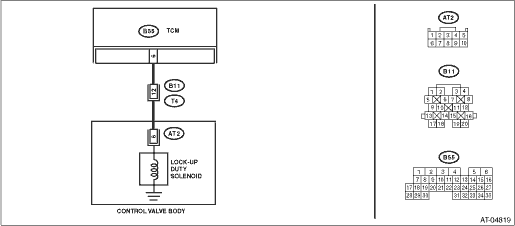
2.CHECK HARNESS CONNECTOR BETWEEN TCM AND TRANSMISSION.
1) Turn the ignition switch to OFF.
2) Disconnect the connectors from TCM and transmission.
3) Measure the resistance of the harness between TCM connector and transmission connector.
Connector & terminal
(B55) No. 6 — (B11) No. 12:
|
Is the resistance less than 1 Ω?
|
|
Repair the open circuit of harness between TCM and transmission connector.
|
3.CHECK HARNESS CONNECTOR BETWEEN TCM AND TRANSMISSION.
Measure the resistance of the harness connector between TCM connector and chassis ground.
Connector & terminal
(B55) No. 6 — Chassis ground:
|
Is the resistance 1 MΩ or more?
|
|
Repair the short circuit of harness between TCM and transmission connector.
|
4.CHECK LOCK-UP DUTY SOLENOID.
Measure the resistance between transmission connector receptacle’s terminals.
|
Is the resistance 2.0 — 6.0 Ω?
|
|
|
5.CHECK OUTPUT SIGNAL FROM TCM USING SUBARU SELECT MONITOR.
1) Connect the connectors to TCM and transmission.
3) Connect the Subaru Select Monitor to the data link connector.
5) Run the Subaru Select Monitor.
6) Warm up the engine until the ATF temperature exceeds 80°C (176°F).
NOTE:
If the ambient temperature is below 0°C (32°F), drive the vehicle until the ATF reaches its operating temperature.
7) Read the data of “Lock Up Duty Ratio” using Subaru Select Monitor.
8) Set the select lever to the “D” range, and slowly increase vehicle speed to 60 km/h (37 MPH).
NOTE:
The speed difference between the front and rear wheels will illuminate the ABS warning light or VDC warning light, but this does not indicate a malfunction. If the warning light illuminates, delete the ABS or VDC memory after completing the AT control diagnosis. 
|
Is the measured value 95%?
|
|
|
6.CHECK OUTPUT SIGNAL FROM TCM USING SUBARU SELECT MONITOR.
Return the engine speed to idling, set the select lever to the “N” range and read the data.
NOTE:
The speed difference between the front and rear wheels will illuminate the ABS warning light or VDC warning light, but this does not indicate a malfunction. If the warning light illuminates, delete the ABS or VDC memory after completing the AT control diagnosis.
|
Is the measured value 0%?
|
Check for poor contact in the TCM and transmission harness or connectors, and repair the fault location.
|
|
7.CHECK FOR POOR CONTACT.
|
Is there poor contact in lock-up duty solenoid circuit?
|
|
Replace the TCM.
|
8.CHECK LOCK-UP DUTY SOLENOID (IN TRANSMISSION).
1) Disconnect the transmission connector.
2) Drain the automatic transmission fluid.
CAUTION:
Do not drain ATF until it cools down.
3) Remove the oil pan, and disconnect the connector from control valve body.
4) Measure the resistance between lock-up duty solenoid and transmission ground.
Connector & terminal
(AT2) No. 6 — Transmission ground:
|
Is the resistance 2.0 — 6.0 Ω?
|
|
Replace the control valve body.
|
9.CHECK HARNESS CONNECTOR BETWEEN LOCK-UP DUTY SOLENOID AND TRANSMISSION.
Measure the resistance of harness between lock-up duty solenoid and transmission connector.
Connector & terminal
(T4) No. 12 — (AT2) No. 6:
|
Is the resistance less than 1 Ω?
|
|
Repair the open circuit of harness between TCM and transmission connector.
|
10.CHECK HARNESS CONNECTOR BETWEEN LOCK-UP DUTY SOLENOID AND TRANSMISSION.
Measure the resistance of harness between transmission connector and transmission ground.
Connector & terminal
(T4) No. 12 — Transmission ground:
|
Is the resistance 1 MΩ or more?
|
Check for poor contact in the lock up duty solenoid and transmission harness or connectors, and repair the fault location.
|
Repair the short circuit of harness between lock-up duty solenoid and transmission connector.
|