AUTOMATIC TRANSMISSION (DIAGNOSTICS)(4AT) > Diagnostic Procedure with Diagnostic Trouble Code (DTC)
DTC DETECTING CONDITION:
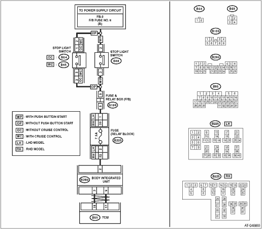
Brake switch malfunction, open input signal circuit
TROUBLE SYMPTOM:
• Gear is not shifted down when driving a down hill.
• Neutral control does not operate.
WIRING DIAGRAM:

|
|
Is DTC of CAN communication displayed?
|
Perform diagnosis according to the DTC.
|
|
2.CHECK FUSE (NO. 8).
1) Turn the ignition switch to OFF.
2) Remove the fuse (No. 8).
|
Is the fuse (No. 8) blown out?
|
Replace the fuse (No. 8). If the replaced fuse (No. 8) has blown out easily, repair the short circuit of harness between fuse (No. 8) and stop light switch.
|
|
3.CHECK FUSE.
Remove the fuse (7.5A) in the relay block.
|
Is the fuse (7.5A) blown out?
|
Replace the fuse (7.5A). If the replaced fuse (7.5A) blows out easily, repair the short circuit in the harness between the fuse (7.5A) and the TCM.
|
|
4.CHECK BODY INTEGRATED UNIT.
1) Turn the ignition switch to OFF.
2) Connect the Subaru Select Monitor to the data link connector.
3) Turn the ignition switch to ON.
4) Run the Subaru Select Monitor.
5) Depress the brake pedal.
6) Read the data of “Stop Light Switch” using Subaru Select Monitor. 
|
|
|
|
5.CHECK TCM.
Read the data of “Stop Light Switch” using Subaru Select Monitor.
|
|
Check for poor contact in the connector or harness, and repair the fault location.
|
Replace the TCM.
|
6.CHECK BODY INTEGRATED UNIT INPUT SIGNAL.
1) Disconnect the connector from body integrated unit.
2) Depress the brake pedal.
3) Measure the voltage of harness between the body integrated unit and chassis ground.
Connector & terminal
(B280) No. 2 (+) — Chassis ground (−):
|
Is the voltage 10 V or more?
|
|
|
7.CHECK HARNESS CONNECTOR BETWEEN BODY INTEGRATED UNIT AND STOP LIGHT SWITCH.
1) Turn the ignition switch to OFF.
2) Disconnect the connector from stop light switch.
3) Measure the resistance of harness between body integrated unit and stop light switch.
Connector & terminal
Without push button start
With cruise control
(B280) No. 2 — (B65) No. 3:
Without cruise control
(B280) No. 2 — (B64) No. 2:
With push button start
(B280) No. 2 — (B65) No. 3:
|
Is the resistance less than 1 Ω?
|
|
Repair the open circuit of harness between body integrated unit and stop light switch.
|
8.CHECK HARNESS CONNECTOR BETWEEN BODY INTEGRATED UNIT AND STOP LIGHT SWITCH.
Measure the resistance of harness between body integrated unit and stop light switch.
Connector & terminal
(B280) No. 2 — Chassis ground:
|
Is the resistance 1 MΩ or more?
|
|
Repair the short circuit of harness between body integrated unit and stop light switch.
|
9.CHECK FOR POOR CONTACT.
|
Is there poor contact in input signal of brake switch?
|
|
Check the body integrated unit.
|