1.CHECK STOP LIGHT & BRAKE SWITCH CIRCUIT.
1) Turn the ignition switch to OFF.
2) Disconnect the stop light & brake switch harness connector.
3) Turn the ignition switch to ON.
4) Measure the voltage between harness connector terminal and chassis ground.
Connector & terminal
(B65) No. 2 (+) — Chassis ground (−):
|
Is the voltage 10 V or more?
|
|
• Check fuse No. 8 (in fuse & relay box).
• Check for open or short circuit in the harness between stop light & brake switch and fuse & relay box.
|
2.CHECK STOP LIGHT & BRAKE SWITCH CIRCUIT.
Measure the voltage between harness connector terminal and chassis ground.
Connector & terminal
(B65) No. 4 (+) — Chassis ground (−):
|
Is the voltage 10 V or more?
|
|
• Check fuse No. 4 (in fuse & relay box).
• Check for open or short circuit in the harness between stop light & brake switch and fuse & relay box.
|
3.CHECK STOP LIGHT & BRAKE SWITCH CIRCUIT.
1) Turn the ignition switch to OFF.
2) Disconnect the harness connector of ECM.
3) Measure the resistance between ECM harness connector terminal and stop light & brake switch harness connector terminal.
Connector & terminal
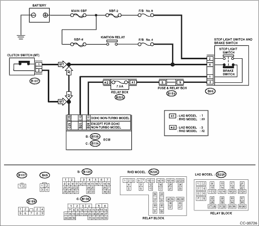
DOHC non-turbo model
(B136) No. 12 — (B65) No. 1:
(B136) No. 13 — (B65) No. 3:
Except for DOHC non-turbo model
(B135) No. 12 — (B65) No. 1:
(B135) No. 13 — (B65) No. 3:
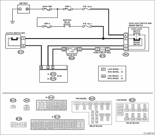
Diesel engine model
(B135) No. 19 — (B65) No. 1:
(B135) No. 18 — (B65) No. 3:
|
Is the resistance less than 10 Ω?
|
|
|
4.CHECK STOP LIGHT & BRAKE SWITCH.
Check the stop light & brake switch. 
|
Is the stop light & brake switch OK?
|
Replace the ECM.
|
Replace the stop light & brake switch.
|