1.CHECK EVAPORATOR SENSOR.
1) Turn the ignition switch to OFF.
3) Disconnect the connector from evaporator sensor.
4) Measure the resistance between terminals of the evaporator sensor.
|
Is the resistance approximately 6.2 kΩ at 0°C (32°F), or approximately 3.3 kΩ at 15°C (59°F) ?
|
|
Replace the evaporator sensor.
|
2.CHECK INPUT SIGNAL FOR EVAPORATOR SENSOR.
1) Turn the ignition switch to ON.
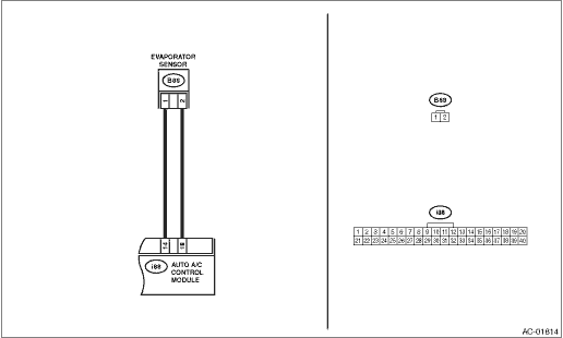
2) Measure the voltage between connector (B88) terminals.
Connector & terminal
(B88) No. 2 (+) — No. 1 (−):
|
Is the voltage approx. 5 V?
|
|
|
3.CHECK AUTO A/C CONTROL MODULE OUTPUT SIGNAL.
1) Turn the ignition switch to OFF.
2) Remove the auto A/C control module.
3) Turn the ignition switch to ON.
4) Measure the voltage between connector terminals of auto A/C control module.
Connector & terminal
(i88) No. 18 (+) — (i88) No. 14 (−):
|
Is the voltage approx. 5 V?
|
|
|
4.CHECK HARNESS CONNECTOR BETWEEN AUTO A/C CONTROL MODULE AND EVAPORATOR SENSOR.
1) Turn the ignition switch to OFF.
2) Disconnect the connector from the auto A/C control module.
3) Measure the resistance of harness between auto A/C control module and evaporator sensor.
Connector & terminal
(B88) No. 2 — (i88) No. 18:
|
Is the resistance less than 1 Ω?
|
|
Repair the open circuit of harness between auto A/C control module and evaporator sensor.
|
5.CHECK HARNESS CONNECTOR BETWEEN AUTO A/C CONTROL MODULE AND EVAPORATOR SENSOR.
Measure the resistance of harness between auto A/C control module and evaporator sensor.
Connector & terminal
(B88) No. 1 — (i88) No. 14:
|
Is the resistance less than 1 Ω?
|
|
Repair the open circuit of harness between auto A/C control module and evaporator sensor.
|
6.CHECK POOR CONTACT.
Check poor contact of auto A/C control module connector.
|
Is there poor contact of connector?
|
|
Replace the auto A/C control module. 
|