1.CHECK AMBIENT SENSOR.
1) Turn the ignition switch to OFF.
2) Disconnect the connector from ambient sensor.
3) Measure the resistance between terminals of ambient sensor.
|
Is the resistance approximately 3 kΩ at 25°C (77°F)?
|
|
Replace the ambient sensor. 
|
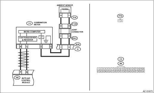
2.CHECK INPUT SIGNAL FOR AMBIENT SENSOR.
1) Turn the ignition to ON.
2) Measure the voltage between connector (F78) terminals.
Connector & terminal
(F78) No. 1 (+) — No. 2 (−):
|
Is the voltage approx. 5 V?
|
|
|
3.CHECK COMBINATION METER OUTPUT SIGNAL.
1) Turn the ignition switch to OFF.
2) Pull out the combination meter.
3) Disconnect the connector from ambient sensor.
4) Turn the ignition switch to ON.
5) Measure the voltage between the combination meter connector terminals.
Connector & terminal
(i10) No. 24 (+) — No. 23 (−):
|
Is the voltage approx. 5 V?
|
|
|
4.CHECK HARNESS CONNECTOR BETWEEN COMBINATION METER AND AMBIENT SENSOR.
1) Turn the ignition switch to OFF.
2) Disconnect the connector from the combination meter.
3) Measure the resistance of harness between combination meter and ambient sensor.
Connector & terminal
(F78) No. 1 — (i10) No. 24:
|
Is the resistance less than 1 Ω?
|
|
Repair the open circuit in the harness between the combination meter and ambient sensor.
|
5.CHECK HARNESS CONNECTOR BETWEEN COMBINATION METER AND AMBIENT SENSOR.
Measure the resistance of harness between combination meter and ambient sensor.
Connector & terminal
(F78) No. 2 — (i10) No. 23:
|
Is the resistance less than 1 Ω?
|
Replace the combination meter.
|
Repair the open circuit in the harness between the combination meter and ambient sensor.
|
6.CHECK HARNESS CONNECTOR BETWEEN COMBINATION METER AND AUTO A/C CONTROL MODULE.
1) Turn the ignition switch to OFF.
2) Disconnect the connector from the combination meter.
3) Disconnect the auto A/C control module connector.
4) Measure the resistance of the harness between the combination meter and auto A/C control module.
Connector & terminal
(i88) No. 19 — (i10) No. 26:
|
Is the resistance less than 1 Ω?
|
|
Repair the open circuit in the harness between the combination meter and auto A/C control module.
|
7.CHECK HARNESS CONNECTOR BETWEEN COMBINATION METER AND AUTO A/C CONTROL MODULE.
Measure the resistance of the harness between the combination meter and auto A/C control module.
Connector & terminal
(i88) No. 20 — (i10) No. 27:
|
Is the resistance less than 1 Ω?
|
|
Repair the open circuit in the harness between the combination meter and auto A/C control module.
|
8.CHECK POOR CONTACT.
Check poor contact of auto A/C control module connector.
|
Is there poor contact of connector?
|
|
Replace the auto A/C control module.
|