1.CHECK FUSE.
1) Turn the ignition switch to OFF.
2) Remove the fuse No. 22 from fuse & relay box.
3) Check the condition of fuse.
|
|
|
|
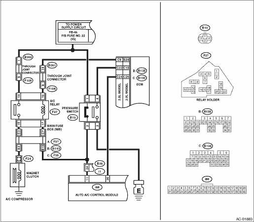
2.CHECK SIGNAL TO A/C RELAY AND AUTO A/C CONTROL MODULE.
1) Disconnect the A/C relay and auto A/C control module harness connector.
2) Turn the ignition switch to ON.
3) Measure the voltage between A/C relay connector terminal and chassis ground.
4) Measure the voltage between auto A/C control module harness connector terminal and chassis ground.
Connector & terminal
(F27) No. 17 (+) — Chassis ground (−):
(i88) No. 11 (+) — Chassis ground (−):
|
Is the voltage 10 V or more?
|
|
|
3.CHECK POWER SUPPLY FOR PRESSURE SWITCH.
1) Turn the ignition switch to OFF.
2) Disconnect the pressure switch harness connector.
3) Turn the ignition switch to ON.
4) Measure the voltage between pressure switch harness connector terminal and chassis ground.
Connector & terminal
(B10) No. 2 (+) — Chassis ground (−):
|
Is the voltage 10 V or more?
|
|
Check for open or short circuit in the harness between fuse and pressure switch.
|
4.CHECK HARNESS BETWEEN PRESSURE SWITCH AND A/C RELAY, AUTO A/C CONTROL MODULE.
1) Turn the ignition switch to OFF.
2) Measure the resistance of harness between pressure switch connector and A/C relay connector.
3) Measure the resistance of harness between pressure switch connector and auto A/C control module connector.
Connector & terminal
(B10) No. 2 — (F27) No. 17:
(B10) No. 2 — (i88) No. 11:
|
Is the resistance less than 1 Ω?
|
Check the pressure switch. 
|
|
5.CHECK POWER SUPPLY FOR A/C RELAY.
Measure the voltage between A/C relay connector terminal and chassis ground.
Connector & terminal
(F27) No. 14 (+) — Chassis ground (−):
|
Is the voltage 10 V or more?
|
|
Check open or short circuit of harness between fuse and A/C relay.
|
6.CHECK A/C RELAY.
Check the A/C relay.
|
|
|
Replace the A/C relay.
|
7.CHECK A/C ON SIGNAL.
1) Turn the ignition switch to OFF.
2) Connect the A/C relay and all disconnected connectors.
3) Start the engine and turn the A/C switch to ON.
4) Turn the temperature control dial at maximum cool position.
5) Measure the voltage between auto A/C control module harness connector terminal and chassis ground.
Connector & terminal
(i88) No. 36 (+) — Chassis ground (−):
|
Is the voltage 5.5 V or more?
|
|
Replace the auto A/C control module.
|
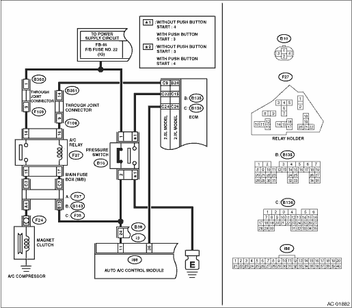
8.CHECK HARNESS BETWEEN AUTO A/C CONTROL MODULE AND ECM.
1) Turn the ignition switch to OFF.
2) Disconnect the harness connector of auto A/C control module and ECM.
3) Measure the resistance of harness between auto A/C control module connector and ECM connector.
Connector & terminal
2.5 L model
(i88) No. 36 — (B136) No. 24:
2.0 L model
(i88) No. 36 — (B136) No. 26:
|
Is the resistance less than 1 Ω?
|
|
|
9.CHECK MAGNET CLUTCH ON SIGNAL.
1) Stop the engine and turn the A/C switch to OFF.
2) Turn the ignition switch to ON.
3) Measure the voltage between ECM connector terminal and chassis ground.
Connector & terminal
2.5 L model
(B136) No. 9 (+) — Chassis ground (−):
2.0 L model
(B135) No. 24 (+) — Chassis ground (−):
|
Is the voltage 10 V or more?
|
|
Check for open or short circuit in the harness between A/C relay and ECM.
|
10.CHECK MAGNET CLUTCH ON SIGNAL.
1) Start the engine and turn the A/C switch to ON.
2) Turn the temperature control dial at maximum cool position.
3) Measure the voltage between ECM connector terminal and chassis ground.
Connector & terminal
2.5 L model
(B136) No. 9 (+) — Chassis ground (−):
2.0 L model
(B135) No. 24 (+) — Chassis ground (−):
|
|
|
Replace the ECM.
|
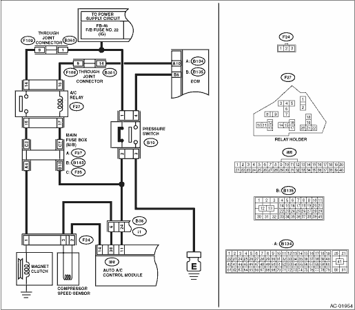
11.CHECK POWER SUPPLY FOR MAGNET CLUTCH.
1) Stop the engine and turn the A/C switch to OFF.
2) Disconnect the harness connector of magnet clutch.
3) Start the engine and turn the A/C switch to ON.
4) Turn the temperature control dial at maximum cool position.
5) Measure the voltage between magnet clutch harness connector terminal and chassis ground.
Connector & terminal
(F24) No. 1 (+) — Chassis ground (−):
|
Is the voltage 10 V or more?
|
Inspect the compressor.
|
Check for open or short circuit in the harness between A/C relay and magnet clutch.
|