1.CHECK FUSE.
1) Turn the ignition switch to OFF.
2) Remove the fuse No. 7 from fuse & relay box.
3) Check the condition of fuse.
|
|
|
|
2.CHECK FUSE.
1) Turn the ignition switch to OFF.
2) Remove the fuse No. 22 and No. 31 from fuse & relay box.
3) Check the condition of fuse.
|
|
|
|
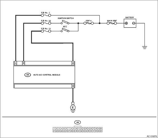
3.CHECK A/C CONTROL UNIT POWER CIRCUIT.
1) Remove the A/C control panel.
2) Disconnect the A/C control panel harness connector.
3) Measure the voltage between A/C control panel harness connector terminal and chassis ground after turning the ignition switch to ACC.
Connector & terminal
(i88) No. 15 (+) — Chassis ground (−):
|
Is the voltage 10 V or more?
|
|
Check for open or short circuit in the harness between A/C control panel and fuse.
|
4.CHECK A/C CONTROL UNIT POWER CIRCUIT.
Measure the voltage between A/C control panel harness connector terminal and chassis ground after turning the ignition switch to ON.
Connector & terminal
(i88) No. 32 (+) — Chassis ground (−):
|
Is the voltage 10 V or more?
|
|
Check for open or short circuit in the harness between A/C control panel and fuse.
|
5.CHECK A/C CONTROL PANEL GROUND POWER CIRCUIT.
Measure the resistance of harness between A/C control panel and chassis ground after turning the ignition switch to OFF.
Connector & terminal
(i88) No. 34 — Chassis ground:
|
Is the resistance less than 10 Ω?
|
|
Repair the harness for ground line.
|
6.CHECK POOR CONTACT.
Check poor contact of auto A/C control module connector.
|
Is there poor contact of connector?
|
|
Replace the auto A/C control module. 
|